E30 Touring 1UZFE V8


 28-11-2011, 06:34 PM
#47
Oderint dum metuant
Thread Starter
Join Date: Mar 2005
Location: You cant have pie without coolWhip
Posts: 693
Likes: 0
Received 0 Likes
on
0 Posts
Cheers gents, fingers crossed it lives up to its potential!
Martooon, I dunno how you do it with the volume of project cars you have on the go at any one time, I am spending so much time on the BMW ive not done anything to the evo in ages
Martooon, I dunno how you do it with the volume of project cars you have on the go at any one time, I am spending so much time on the BMW ive not done anything to the evo in ages

 04-12-2011, 06:09 PM
#49
Oderint dum metuant
Thread Starter
Join Date: Mar 2005
Location: You cant have pie without coolWhip
Posts: 693
Likes: 0
Received 0 Likes
on
0 Posts
Not a great deal of progress today, it was mainly modifying the petrol tank and trans tunnel to take the larger diameter prop shaft without fouling.
However, I found out that david had made a useful gadget for his other half, to help with making pasta of all things!
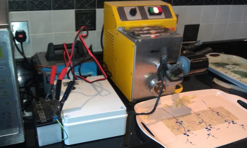
Yes, that is a window wiper motor, the intermitent control system, a motorcycle battery and a cut down steel rule....
http://smg.photobucket.com/albums/v6...=VIDEO0017.mp4
Much better than having to stand there and cut the pasta by hand! Superb use of spares too.
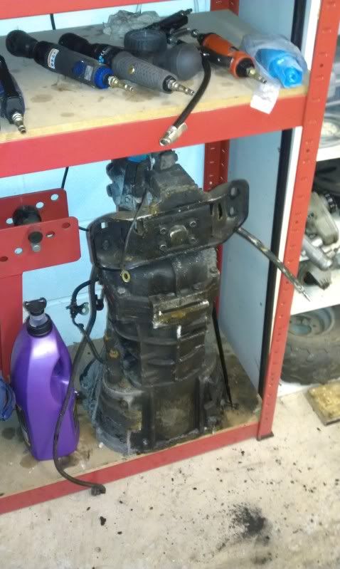
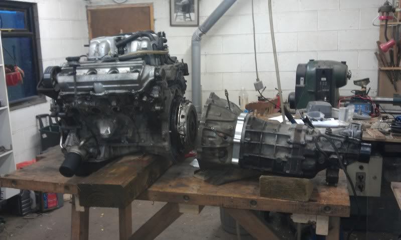
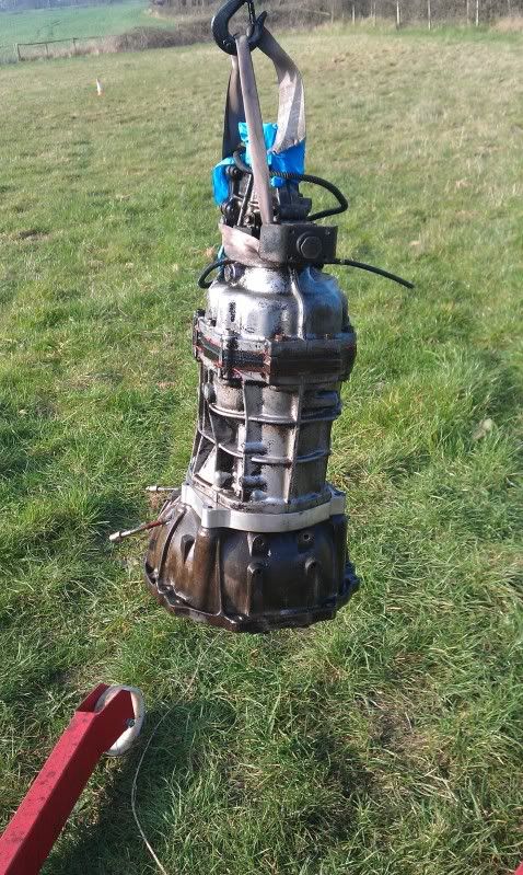
Anyway, after the tunnel mods, it was on to splitting our spare gearbox from the donor engine, which is on ebay as we speak lol, so that its all ready for collection.
Started off like this...........
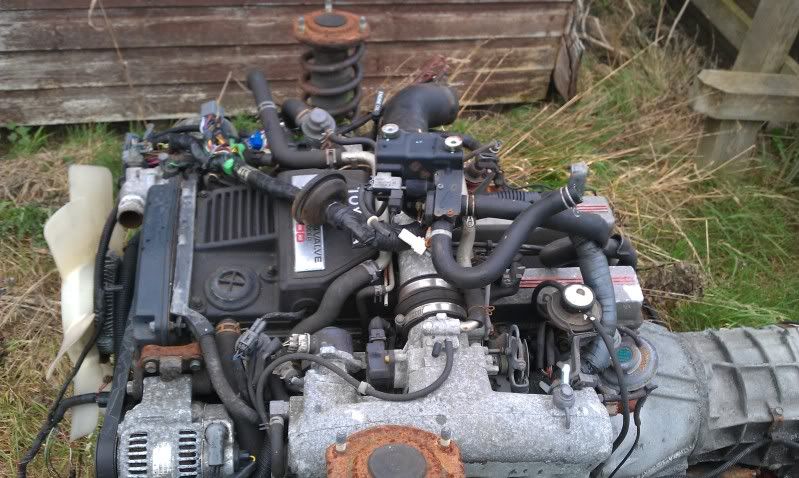
Took some man handling to get it in to the workshop.....
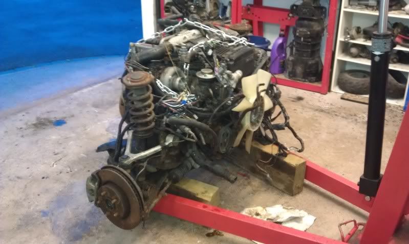
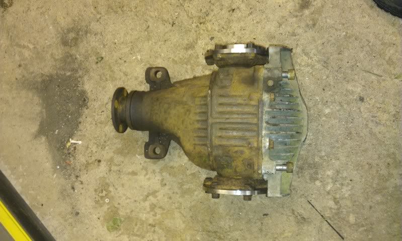
Now looks like this......
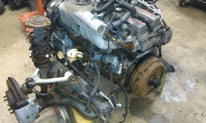
Leaving us with this!.....
Anyway, next weekend will hopefully see the drive train all done, and on to something a little more exciting. I hope.
However, I found out that david had made a useful gadget for his other half, to help with making pasta of all things!
Yes, that is a window wiper motor, the intermitent control system, a motorcycle battery and a cut down steel rule....
http://smg.photobucket.com/albums/v6...=VIDEO0017.mp4
Much better than having to stand there and cut the pasta by hand! Superb use of spares too.
Anyway, after the tunnel mods, it was on to splitting our spare gearbox from the donor engine, which is on ebay as we speak lol, so that its all ready for collection.
Started off like this...........
Took some man handling to get it in to the workshop.....
Now looks like this......
Leaving us with this!.....
Anyway, next weekend will hopefully see the drive train all done, and on to something a little more exciting. I hope.
11-12-2011, 06:43 PM
#50
Oderint dum metuant
Thread Starter
Join Date: Mar 2005
Location: You cant have pie without coolWhip
Posts: 693
Likes: 0
Received 0 Likes
on
0 Posts
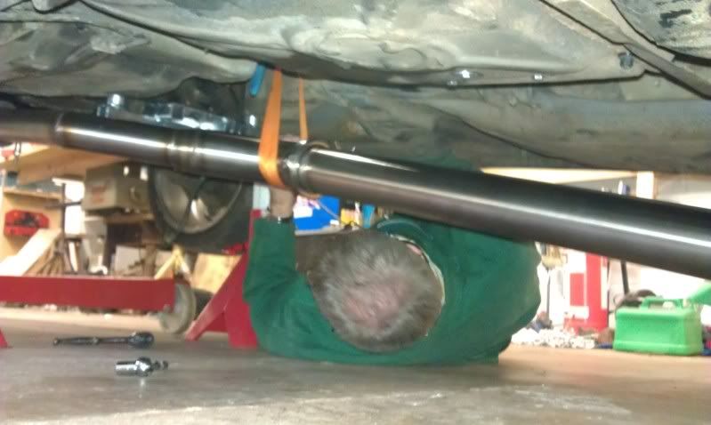
Right, after last weeks' lack of real progress, this week has been much more fruitful.
Continued with the drive train first, and after making clearance for the massive prop, moved on to the 2nd driveshaft adaptor. Leaving the diff looking like this......
We then fitted the driveshafts and dropped the car, to find that the passenger side drive shaft was now too long.
After some re-measuring to ensure that a mistake had not been made, it turns out that our assumption that the standard shafts were different lengths (to account for the offset diff) was in error. So standard shafts being equal length means that one side fits lovely with the spacer, and the other is too long by roughly 20mm.
So on to some drive shaft mods..........

Which sorted the problem and means that the car now moves under its own power! Woohoo!
So, with all that sorted, we stripped the car (again) so that the final brackets etc could be sent for galvanizing. Additionally it gives me chance to take and post some pics that were missing from the early part of the build.....
Bay looking empty:

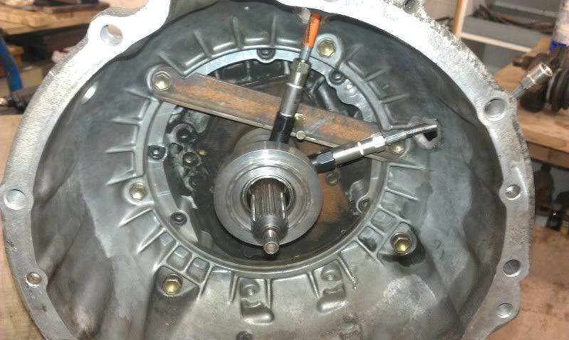
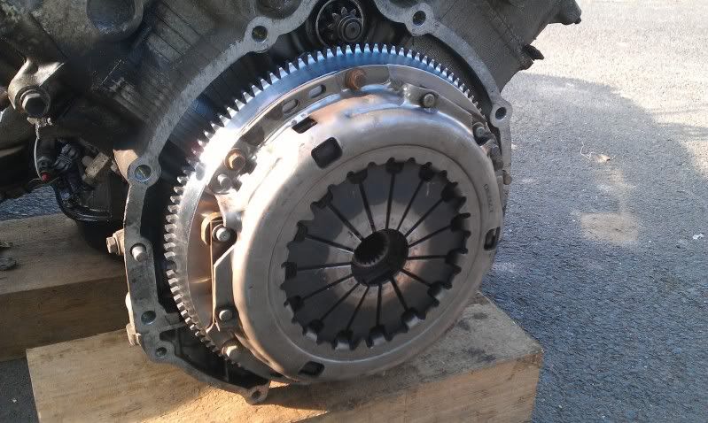
Engine and box just split:
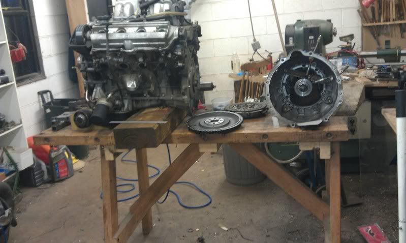
Bit of a close up of the CSC and its modded bearing face:
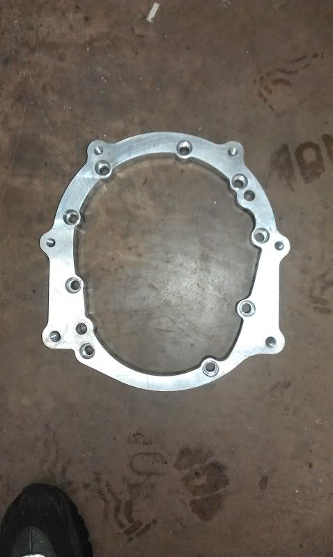
and finally the spacer plate that joins the R154 to 1UZ auto bell housing:
Next week we should start working on either the cooling system, brake system or exhaust system, depending on which parts arrive 1st!
Continued with the drive train first, and after making clearance for the massive prop, moved on to the 2nd driveshaft adaptor. Leaving the diff looking like this......
We then fitted the driveshafts and dropped the car, to find that the passenger side drive shaft was now too long.
After some re-measuring to ensure that a mistake had not been made, it turns out that our assumption that the standard shafts were different lengths (to account for the offset diff) was in error. So standard shafts being equal length means that one side fits lovely with the spacer, and the other is too long by roughly 20mm.
So on to some drive shaft mods..........
Which sorted the problem and means that the car now moves under its own power! Woohoo!
So, with all that sorted, we stripped the car (again) so that the final brackets etc could be sent for galvanizing. Additionally it gives me chance to take and post some pics that were missing from the early part of the build.....
Bay looking empty:
Engine and box just split:
Bit of a close up of the CSC and its modded bearing face:
and finally the spacer plate that joins the R154 to 1UZ auto bell housing:
Next week we should start working on either the cooling system, brake system or exhaust system, depending on which parts arrive 1st!
01-01-2012, 04:42 PM
#51
Oderint dum metuant
Thread Starter
Join Date: Mar 2005
Location: You cant have pie without coolWhip
Posts: 693
Likes: 0
Received 0 Likes
on
0 Posts
Right, firstly happy new year folks!
We managed to fit in some time on the car between doing the respective family things, so here is the progress david and I made over the festive period.....
The brake and exhaust parts we were waiting for didnt turn up as early as expected, so we decided to get the rad mounted as a fill in job to begin with. So front end off!
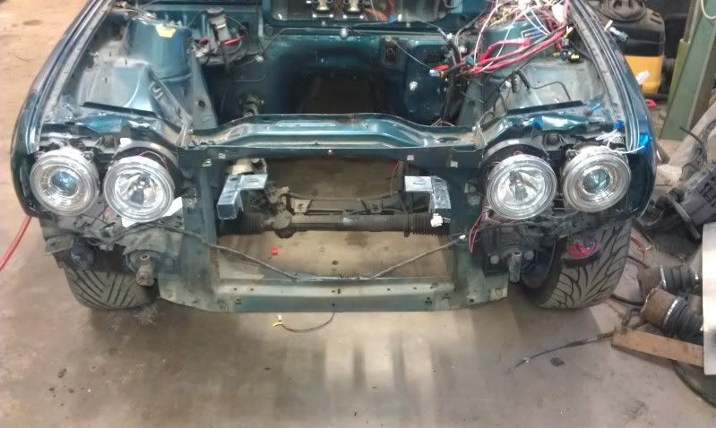
Then rad mounted much further forward than is standard:
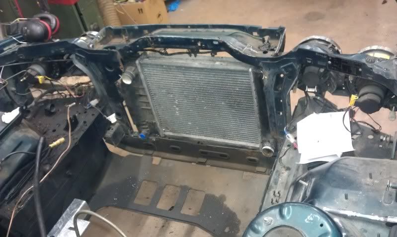
Its just held in with lock wire in these pictures, but some brackets are on the "to do" list.
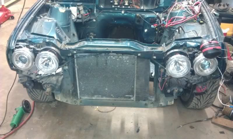
Then some bumper mods to let in as much air as poss....
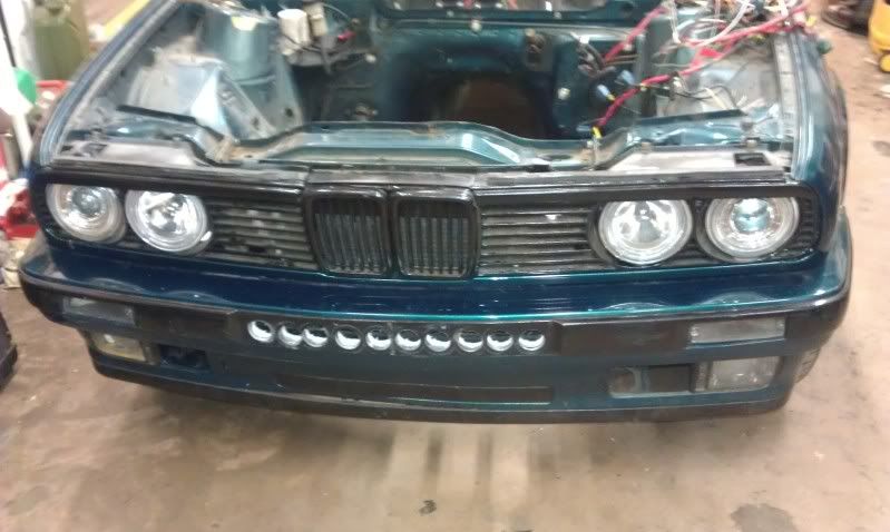
What this pic doesnt show is the huge hole that has been chopped out behind the bumper, so hopefully the flow should be adequate to cool the V8. (This is a bit of an optimistic opinion, but if push comes to shove, a 2nd rad in the rear can be installed)
Then the brake parts arrived, so we started work on getting the car to stop!
This:
Plus this:
Equals this:
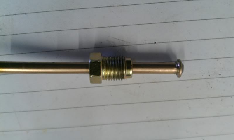
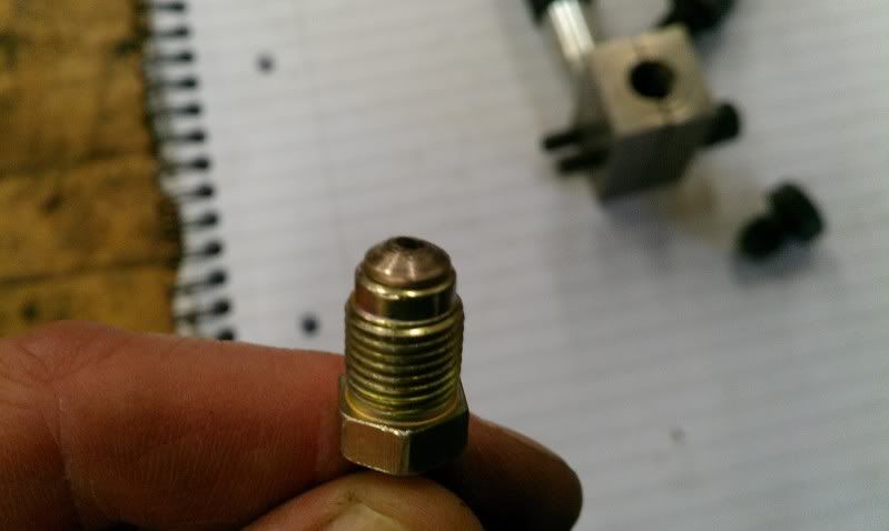
Making hard lines is much easier and cheaper than messing with -3 braided hose, so the whole system will be done using hard pipes.
The system will be as shown here:
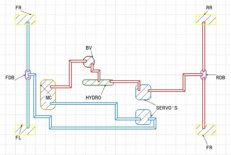
As you can see, both circuits of the master cylinder will be used, with one circuit heading to a remote servo, then to a distribution block and finally to each front caliper.
The rear circuit is a touch more complex, with the fluid exiting the 2nd master cylinder union, heading to the bias valve, then to the hydro, out of the hydro to the 2nd remote servo and to the rear wheels via a 2nd distribution block.
The system was designed this way so that we could have adjustable rear brake bias, whilst at the same time having a hydro for the rears that is servo assisted and therefore very effective at locking the rears. We hope.
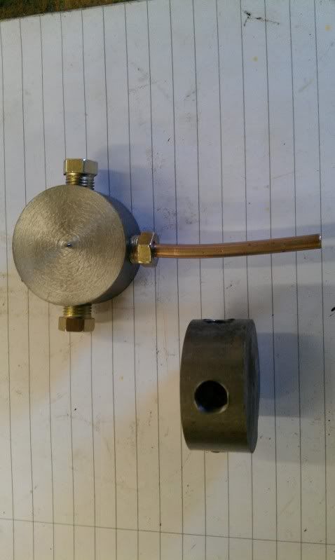
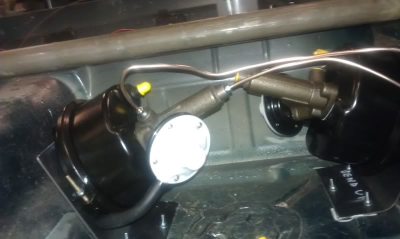
So, distribution blocks. Start with this:
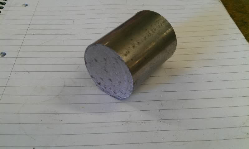
A little milling machine action:
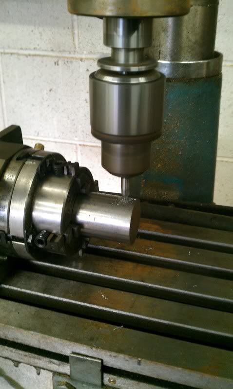
Followed by some tidying, and we ended up with these:
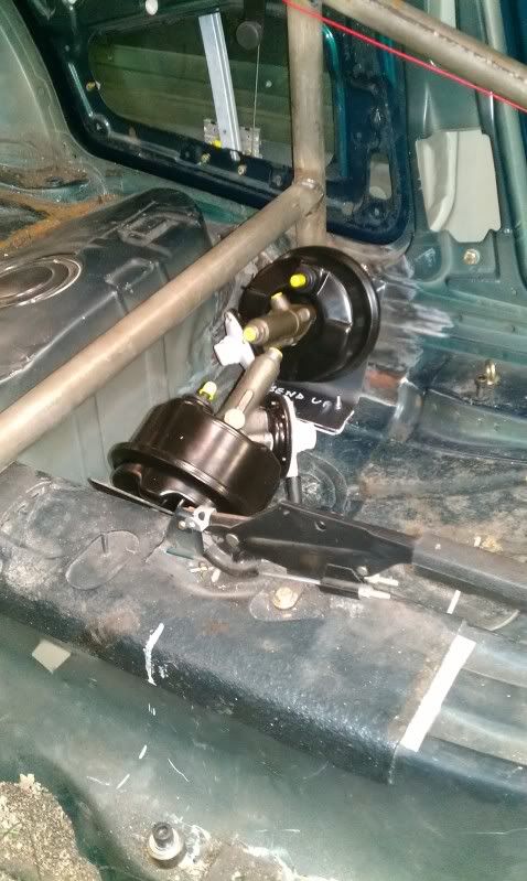
Then we needed to knock up some brackets to mount the remote servos:
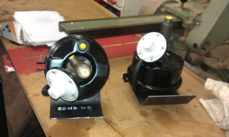
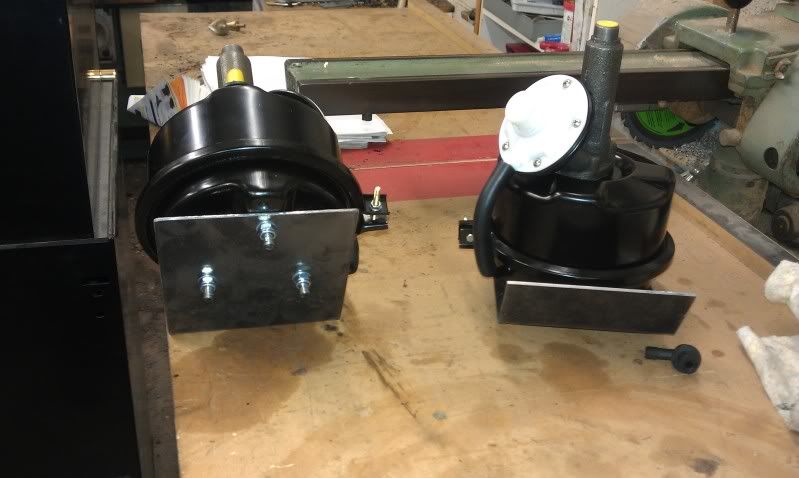
Which then needed to be mounted in the car:
Then we moved on to the pipe work. Excuse the dodgy bends, they will be much nicer!
We also needed to mount the bias valve and hydo wand:
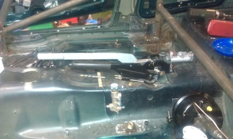
With that all done, we managed to get everything piped up quite late on in the day and were able to test everything out.
Even without vacuum to the remote servo units, the brakes feel nice, and the hydro wand works at least as well as the standard hand brake, so everything should be sweet!
Next time, some exhaust work. I hope.
We managed to fit in some time on the car between doing the respective family things, so here is the progress david and I made over the festive period.....
The brake and exhaust parts we were waiting for didnt turn up as early as expected, so we decided to get the rad mounted as a fill in job to begin with. So front end off!
Then rad mounted much further forward than is standard:
Its just held in with lock wire in these pictures, but some brackets are on the "to do" list.
Then some bumper mods to let in as much air as poss....
What this pic doesnt show is the huge hole that has been chopped out behind the bumper, so hopefully the flow should be adequate to cool the V8. (This is a bit of an optimistic opinion, but if push comes to shove, a 2nd rad in the rear can be installed)
Then the brake parts arrived, so we started work on getting the car to stop!
This:
Plus this:
Equals this:
Making hard lines is much easier and cheaper than messing with -3 braided hose, so the whole system will be done using hard pipes.
The system will be as shown here:
As you can see, both circuits of the master cylinder will be used, with one circuit heading to a remote servo, then to a distribution block and finally to each front caliper.
The rear circuit is a touch more complex, with the fluid exiting the 2nd master cylinder union, heading to the bias valve, then to the hydro, out of the hydro to the 2nd remote servo and to the rear wheels via a 2nd distribution block.
The system was designed this way so that we could have adjustable rear brake bias, whilst at the same time having a hydro for the rears that is servo assisted and therefore very effective at locking the rears. We hope.
So, distribution blocks. Start with this:
A little milling machine action:
Followed by some tidying, and we ended up with these:
Then we needed to knock up some brackets to mount the remote servos:
Which then needed to be mounted in the car:
Then we moved on to the pipe work. Excuse the dodgy bends, they will be much nicer!
We also needed to mount the bias valve and hydo wand:
With that all done, we managed to get everything piped up quite late on in the day and were able to test everything out.
Even without vacuum to the remote servo units, the brakes feel nice, and the hydro wand works at least as well as the standard hand brake, so everything should be sweet!
Next time, some exhaust work. I hope.
 16-01-2012, 05:13 PM
#55
Oderint dum metuant
Thread Starter
Join Date: Mar 2005
Location: You cant have pie without coolWhip
Posts: 693
Likes: 0
Received 0 Likes
on
0 Posts
Right, manifold time...
We only really had time to work on saturday, so the manifolds are only around half done, but something is better than nothing!
We started off with our laser cut flanges and some cast iron stainless steel bends, below:
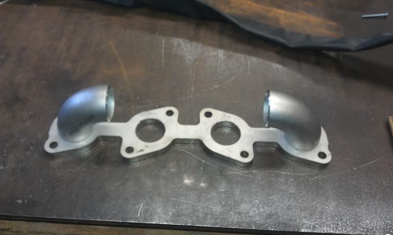
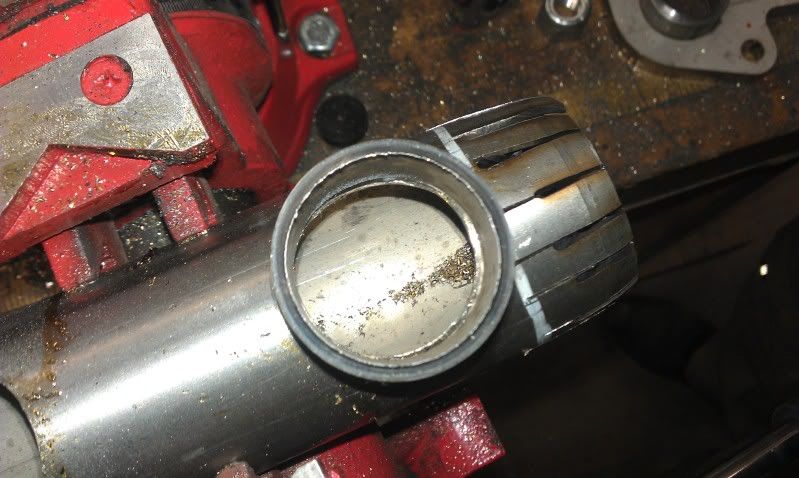
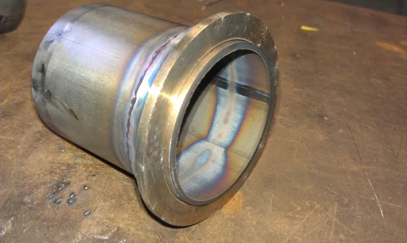
We then sourced some larger diameter stainless tube to act as a log/collector due to space issues. With it being a larger diameter, we needed a nice way to mate it to the cast bends, so we chopped it along the axis:
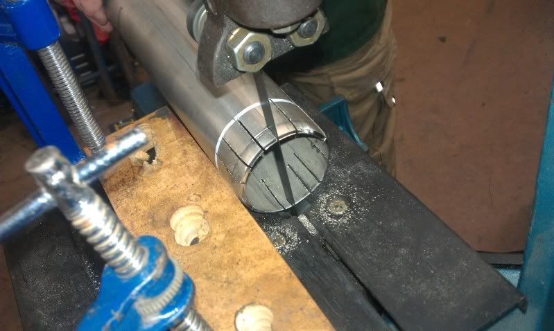
and then some careful tapping (read, hit it with a hammer) to get this:
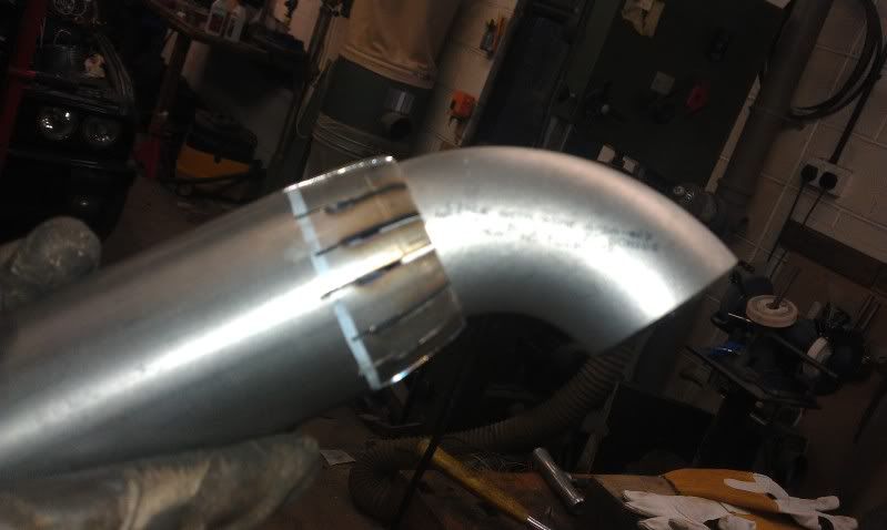
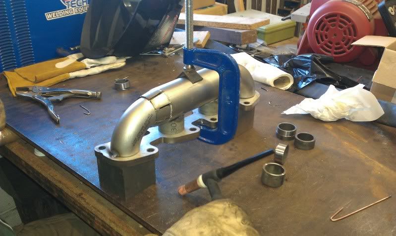
Do the same on the other side and offer up to the flange:
Then hole saw the centre ports:
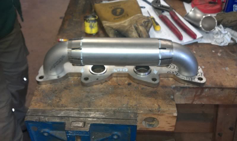
Tack it all together and offer it up to the engine:
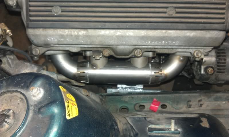
It all fits, so weld all of the cuts and joins etc:
Granted it needs some finishing to look nice (please dont judge me on this picture):
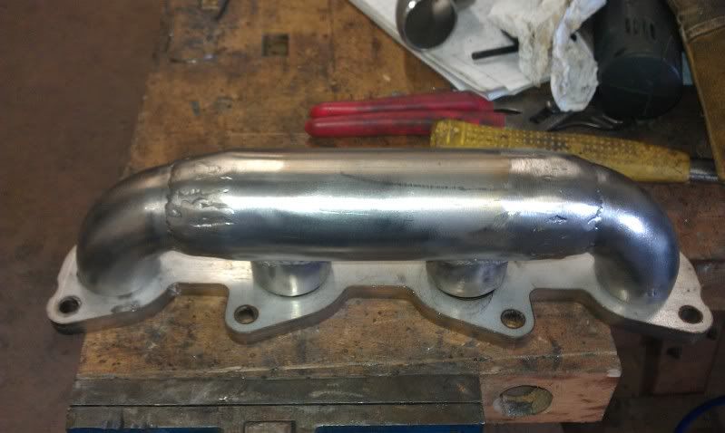
So its effectively there or there abouts!
More next week I hope.
We only really had time to work on saturday, so the manifolds are only around half done, but something is better than nothing!
We started off with our laser cut flanges and some cast iron stainless steel bends, below:
We then sourced some larger diameter stainless tube to act as a log/collector due to space issues. With it being a larger diameter, we needed a nice way to mate it to the cast bends, so we chopped it along the axis:
and then some careful tapping (read, hit it with a hammer) to get this:
Do the same on the other side and offer up to the flange:
Then hole saw the centre ports:
Tack it all together and offer it up to the engine:
It all fits, so weld all of the cuts and joins etc:
Granted it needs some finishing to look nice (please dont judge me on this picture):
So its effectively there or there abouts!
More next week I hope.
 17-01-2012, 09:48 AM
#59
Oderint dum metuant
Thread Starter
Join Date: Mar 2005
Location: You cant have pie without coolWhip
Posts: 693
Likes: 0
Received 0 Likes
on
0 Posts
22-01-2012, 07:36 PM
#60
Oderint dum metuant
Thread Starter
Join Date: Mar 2005
Location: You cant have pie without coolWhip
Posts: 693
Likes: 0
Received 0 Likes
on
0 Posts
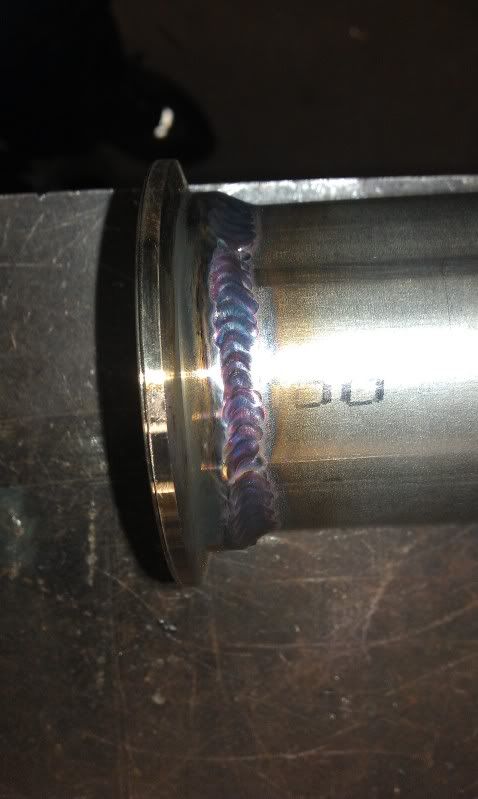
More work on the manifolds and down pipes today, not a great deal to show for it though, as most of the day was spent TIG welding.
As seen here:
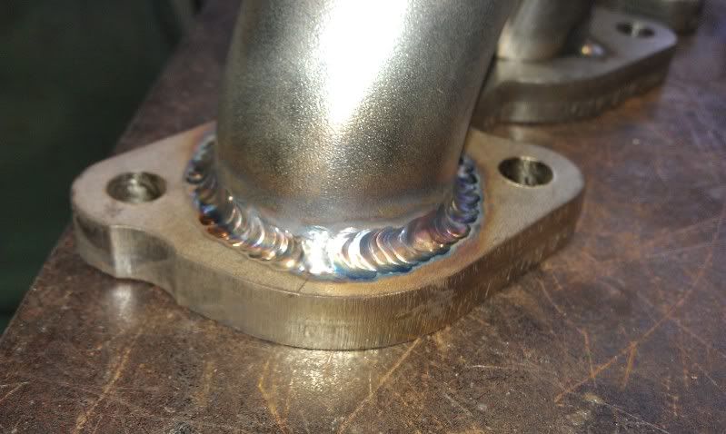
Possibly a little scrappy, but ok considering its cast 304 stainless to plate 316 stainless.
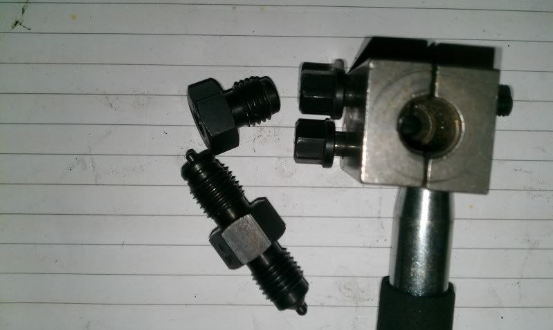
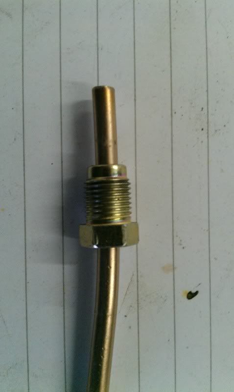
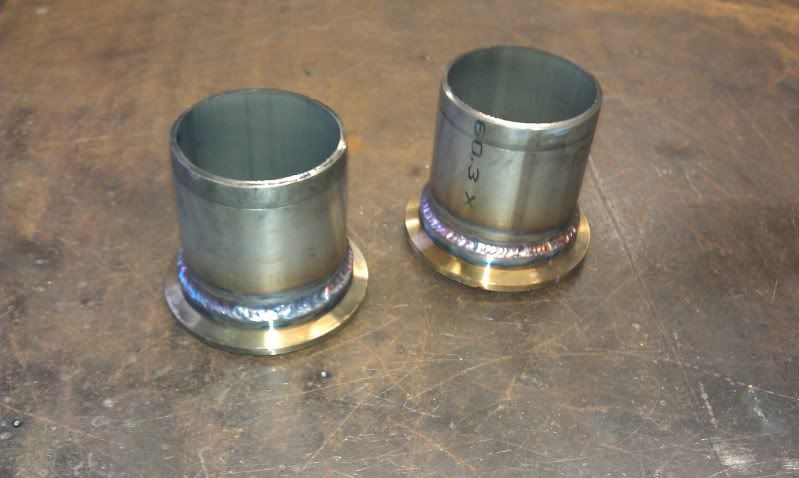
Also had some exhaust goodies arrive:
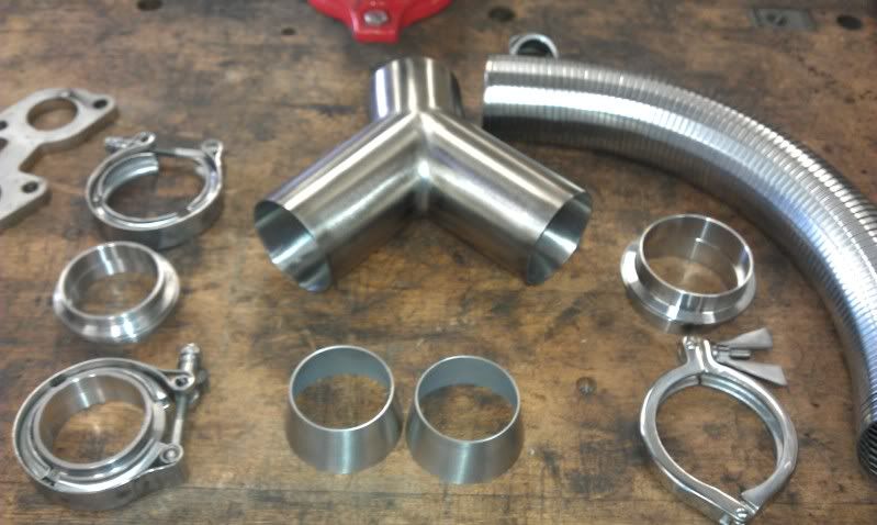
Although the Y piece is the same OD at each branch, this is reduced using these tapers:
I am sure there will be more visible work done next weekend, so fingers crossed there will be more to show.
As seen here:
Possibly a little scrappy, but ok considering its cast 304 stainless to plate 316 stainless.
Also had some exhaust goodies arrive:
Although the Y piece is the same OD at each branch, this is reduced using these tapers:
I am sure there will be more visible work done next weekend, so fingers crossed there will be more to show.
29-01-2012, 06:44 PM
#61
Oderint dum metuant
Thread Starter
Join Date: Mar 2005
Location: You cant have pie without coolWhip
Posts: 693
Likes: 0
Received 0 Likes
on
0 Posts
Yet more time on the TIG for David and I today.
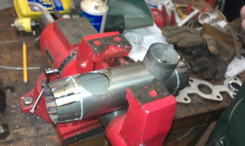
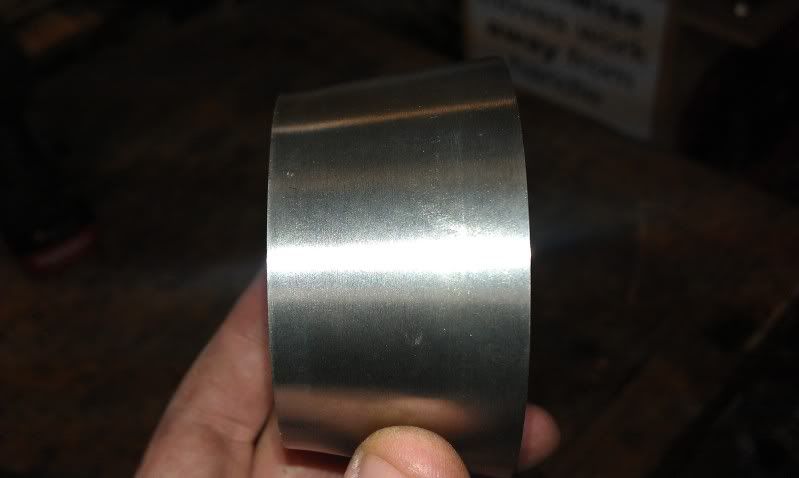
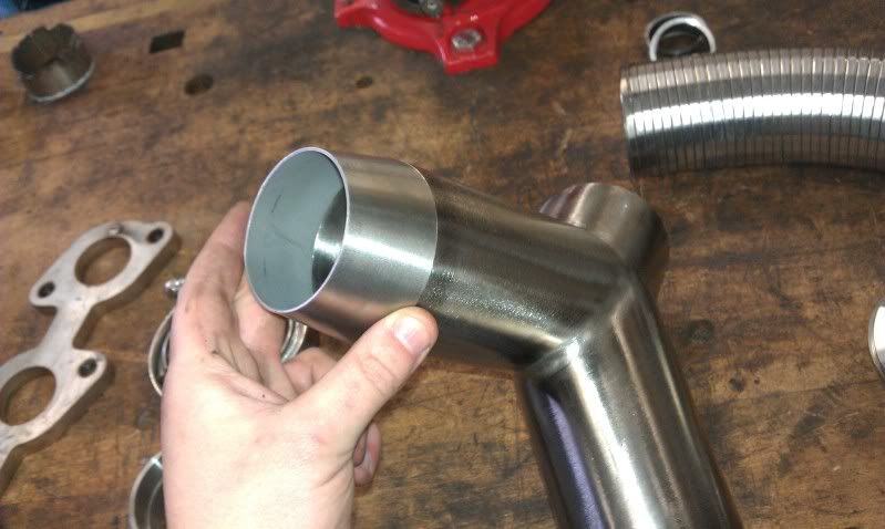
Started by making some cheapo V bands in to self centering ones, by knocking some exhaust tube through until it protrudes by a few mm:
Then needed to knock up the down pipes and bridging section of the exhaust, so after a long time welding here it is:
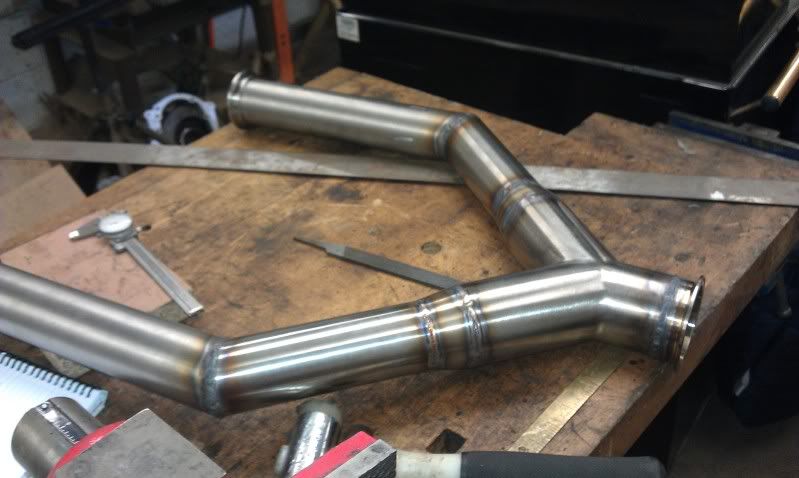
Getting the hang of this TIG lark:
By this time, most of the day was gone, so we decided to get it in to position using some ratchet straps, V band it all together and see how it looked:
Thats both banks in to down pipes and a Y piece, in to a 3" 316L section that terminates just by the diff. Next weekend may see it completed with a silencer, but until then we couldnt resist a little video to see how it looked/sounded.
Bear in mind that this is from my mobile phone and the mic cant cope with unsilenced V8'ness, but take my word, it sounds savage!
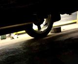
Anyway, more next week hopefully.
Started by making some cheapo V bands in to self centering ones, by knocking some exhaust tube through until it protrudes by a few mm:
Then needed to knock up the down pipes and bridging section of the exhaust, so after a long time welding here it is:
Getting the hang of this TIG lark:
By this time, most of the day was gone, so we decided to get it in to position using some ratchet straps, V band it all together and see how it looked:
Thats both banks in to down pipes and a Y piece, in to a 3" 316L section that terminates just by the diff. Next weekend may see it completed with a silencer, but until then we couldnt resist a little video to see how it looked/sounded.
Bear in mind that this is from my mobile phone and the mic cant cope with unsilenced V8'ness, but take my word, it sounds savage!
Anyway, more next week hopefully.

 26-02-2012, 10:54 AM
#66
Oderint dum metuant
Thread Starter
Join Date: Mar 2005
Location: You cant have pie without coolWhip
Posts: 693
Likes: 0
Received 0 Likes
on
0 Posts
Not a great deal going on lately, apart from a silencing frenzy.
Basically we set up an experiment, consisting of a decibel meter placed 1 meter away from the exhaust opening, at 45 degrees. The engine was then held at 2750 ish rpm, and an unsilenced sound pressure level was recorded.
Unsilenced - 101.5 dbc
The test was then repeated, but including a 3" straight through stainless silencer.
Silenced - 100.5 dbc
Granted, the decibel scale is logarithmic, but I was expecting a larger reduction than that! So, we either need 8 of these silencers or we need a rethink......
Loud is an understatement.
Basically we set up an experiment, consisting of a decibel meter placed 1 meter away from the exhaust opening, at 45 degrees. The engine was then held at 2750 ish rpm, and an unsilenced sound pressure level was recorded.
Unsilenced - 101.5 dbc
The test was then repeated, but including a 3" straight through stainless silencer.
Silenced - 100.5 dbc
Granted, the decibel scale is logarithmic, but I was expecting a larger reduction than that! So, we either need 8 of these silencers
or we need a rethink......Loud is an understatement.
 21-03-2012, 07:02 PM
#68
Oderint dum metuant
Thread Starter
Join Date: Mar 2005
Location: You cant have pie without coolWhip
Posts: 693
Likes: 0
Received 0 Likes
on
0 Posts
No time for any progress lately, but today something good turned up in the post!!
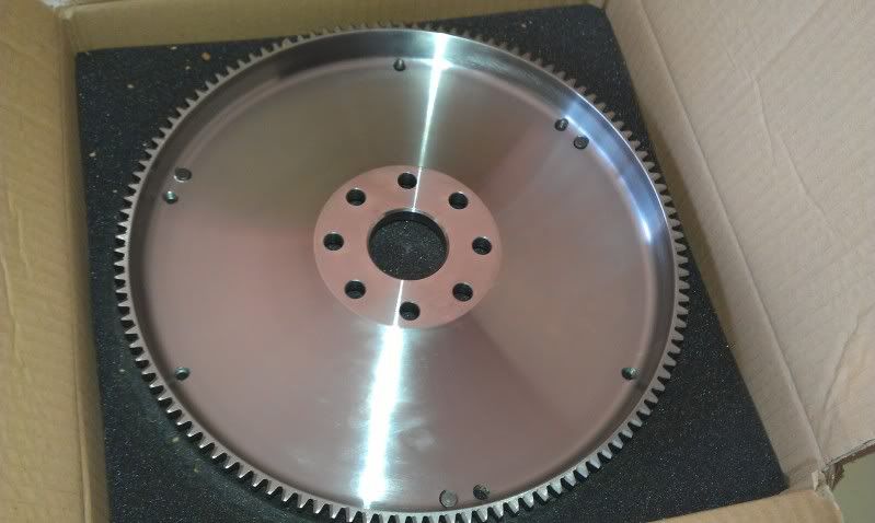
It took a while to arrive, but looks like it will be worth the wait. Weighs less than 5kg too
It took a while to arrive, but looks like it will be worth the wait. Weighs less than 5kg too
 21-03-2012, 07:15 PM
#70
Oderint dum metuant
Thread Starter
Join Date: Mar 2005
Location: You cant have pie without coolWhip
Posts: 693
Likes: 0
Received 0 Likes
on
0 Posts
22-03-2012, 08:41 PM
#72
Oderint dum metuant
Thread Starter
Join Date: Mar 2005
Location: You cant have pie without coolWhip
Posts: 693
Likes: 0
Received 0 Likes
on
0 Posts
Another little update, this time illustrating why I have had no time to work on the BMW lately....
Essentially, a friend asked if I could take a look at his uprights with a view to relocating the outboard pick up points and changing the type of bearing used.
After a load of reverse engineering of the original upright in order to determine its strength and stiffness, both empirically and in CAD/FEA, and a load of dynamics simulation to determine optimal pick up point location for this application, as well as real world load cases for physical testing, this is the end result.........
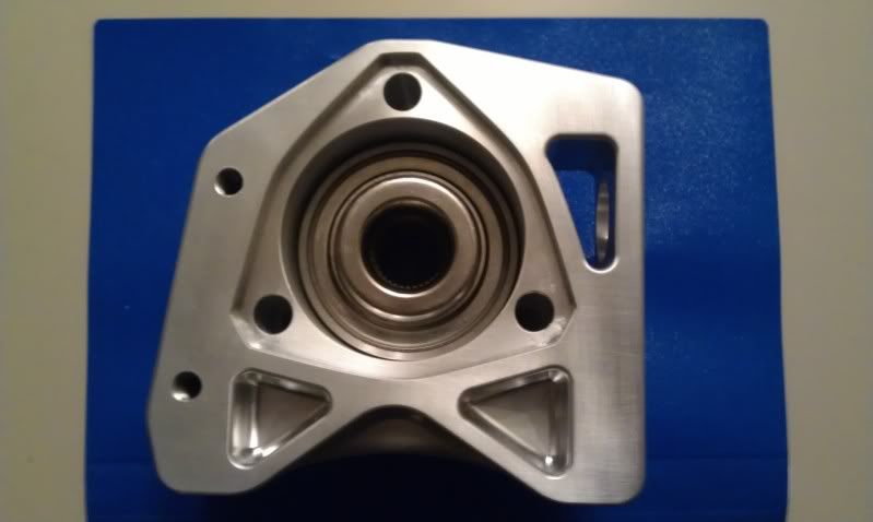
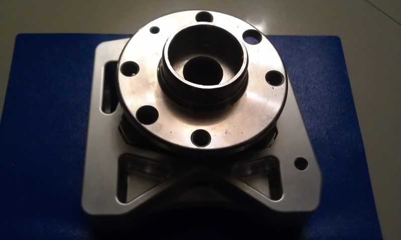
Sorry about the poor pictures, but the camera on my mobile is playing up!
Just thought I would share, as I am quite proud of the results
Essentially, a friend asked if I could take a look at his uprights with a view to relocating the outboard pick up points and changing the type of bearing used.
After a load of reverse engineering of the original upright in order to determine its strength and stiffness, both empirically and in CAD/FEA, and a load of dynamics simulation to determine optimal pick up point location for this application, as well as real world load cases for physical testing, this is the end result.........
Sorry about the poor pictures, but the camera on my mobile is playing up!
Just thought I would share, as I am quite proud of the results
 24-03-2012, 08:16 PM
#75
Oderint dum metuant
Thread Starter
Join Date: Mar 2005
Location: You cant have pie without coolWhip
Posts: 693
Likes: 0
Received 0 Likes
on
0 Posts
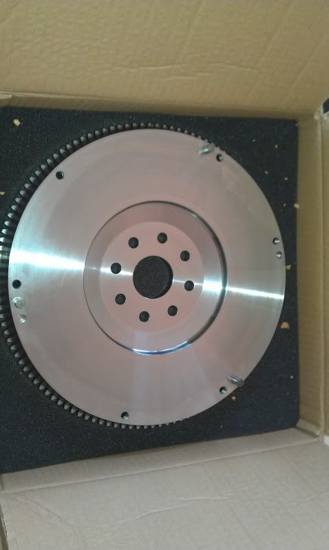
Took advantage of the weather today to whip the engine and box out.
Box being cleaned, as its filthy.....
Then flywheel and clutch on......
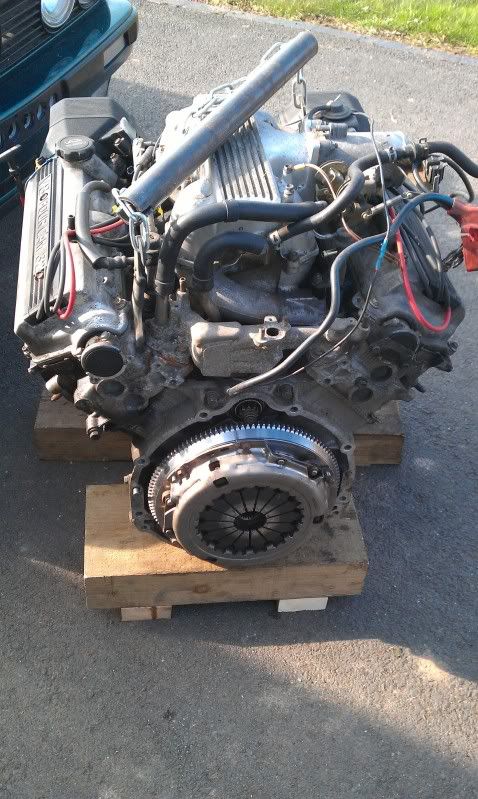
And its all back in the car now ready for the prop, diff and shafts to be fitted next weekend!
Box being cleaned, as its filthy.....
Then flywheel and clutch on......
And its all back in the car now ready for the prop, diff and shafts to be fitted next weekend!
25-03-2012, 03:42 PM
#76
Oderint dum metuant
Thread Starter
Join Date: Mar 2005
Location: You cant have pie without coolWhip
Posts: 693
Likes: 0
Received 0 Likes
on
0 Posts
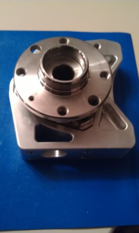
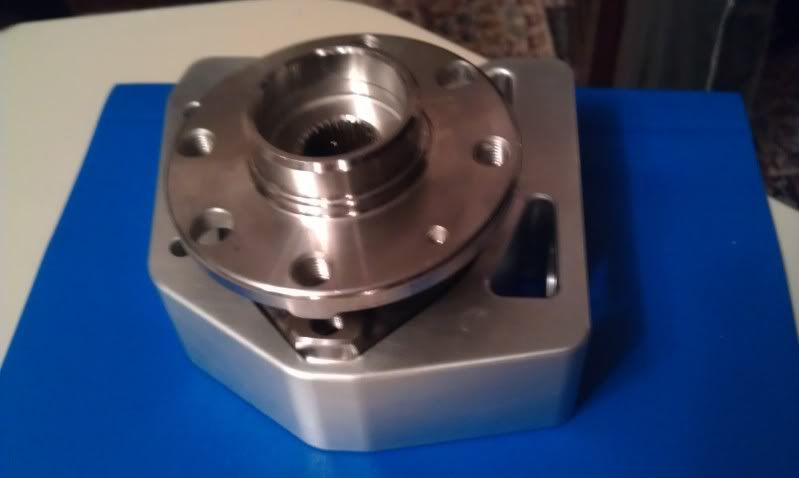
Had a bit of a trial fit of the new upright today, works well apart from some minor teething troubles.
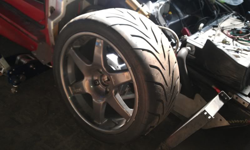
Wish bone angles now look a lot more sensible, even if it is a little hard to tell from my dodgy pictures....
Original:
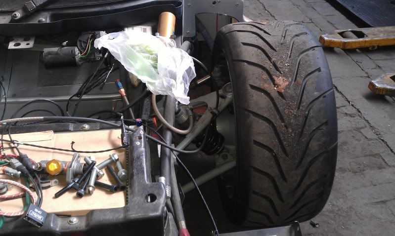
New:
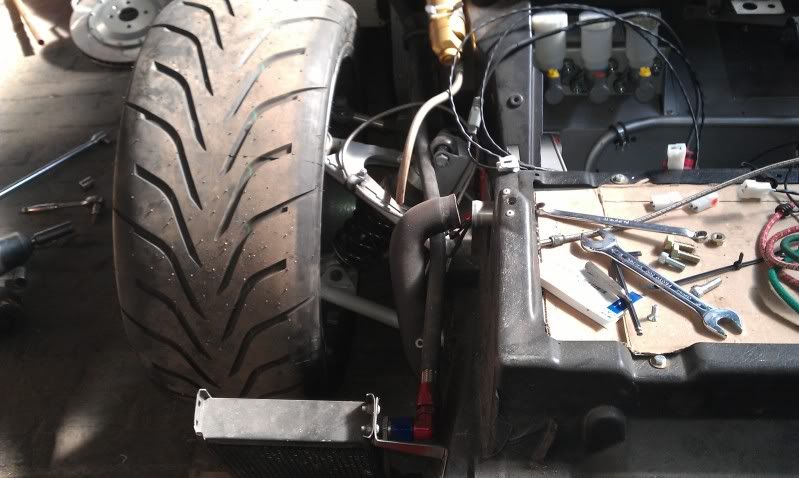
Fingers crossed that this sorts the issues!
Wish bone angles now look a lot more sensible, even if it is a little hard to tell from my dodgy pictures....
Original:
New:
Fingers crossed that this sorts the issues!
14-05-2012, 08:41 AM
#78
Oderint dum metuant
Thread Starter
Join Date: Mar 2005
Location: You cant have pie without coolWhip
Posts: 693
Likes: 0
Received 0 Likes
on
0 Posts
Right, long break over (during which, I finished my dissertation and David made a guitar, from scratch!) so bit of a minor update from sunday.
The prop clearance to the fuel tank was a nagging concern to both David and I, so we decided to rip it out and do a proper fuel system. So, tank and swirl pot ordered, and after some flow rate testing a Honda CBR1000 motorcycle pump was selected for the lift between the two.
In the car:
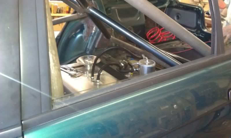
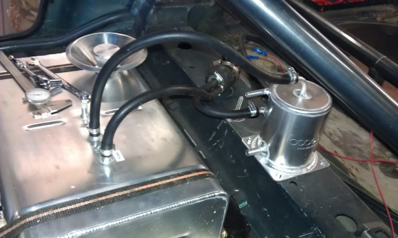
Also did some further welding on the exhaust system, no pics at the minute, to incorporate a centre silencer and huge repackable backbox across the width of the boot floor.
Next weekend should see the exhaust all finished off, and provided we can source an 044, fingers crossed it will run on the new fuel system.
The prop clearance to the fuel tank was a nagging concern to both David and I, so we decided to rip it out and do a proper fuel system. So, tank and swirl pot ordered, and after some flow rate testing a Honda CBR1000 motorcycle pump was selected for the lift between the two.
In the car:
Also did some further welding on the exhaust system, no pics at the minute, to incorporate a centre silencer and huge repackable backbox across the width of the boot floor.
Next weekend should see the exhaust all finished off, and provided we can source an 044, fingers crossed it will run on the new fuel system.