Help with wiring please, pics added
 22-06-2011, 08:22 PM
#1
Help with wiring please
I have a kit car running a pinto engine, ive removed the engine to have it rebuilt etc and to tidy the car up, basically the wiring was already done and is in bit of a mess so im tidying it up, just want to make sure what im using is right and wired up correctly.
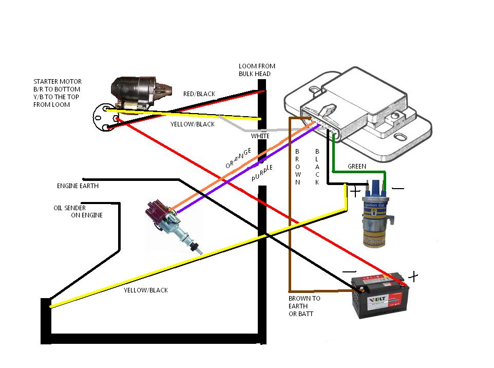
It has a motorcraft ignition module with the following wires
brown
green
white
orange
purple
black
the brown is wired to ground,
green -ve side of group a style coil
white cut not used
orange cut not used
purpel cut not used
black +ve side of coil
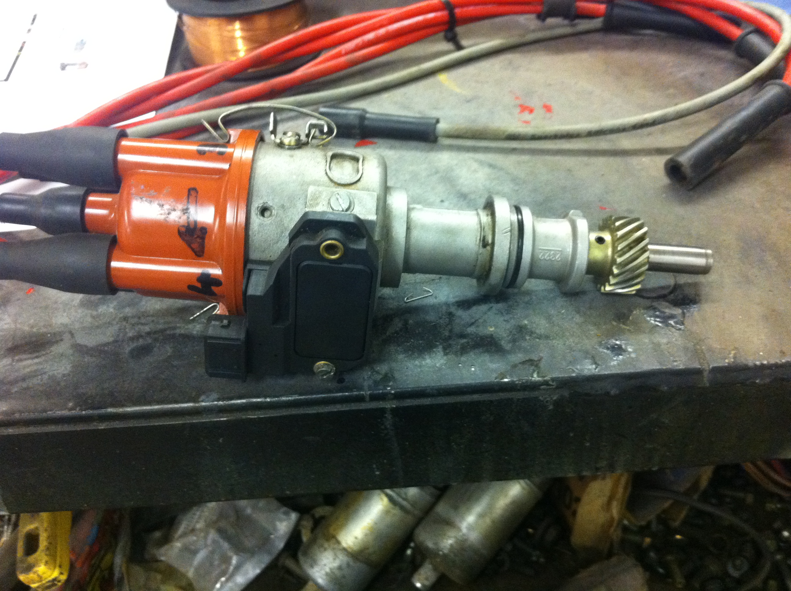
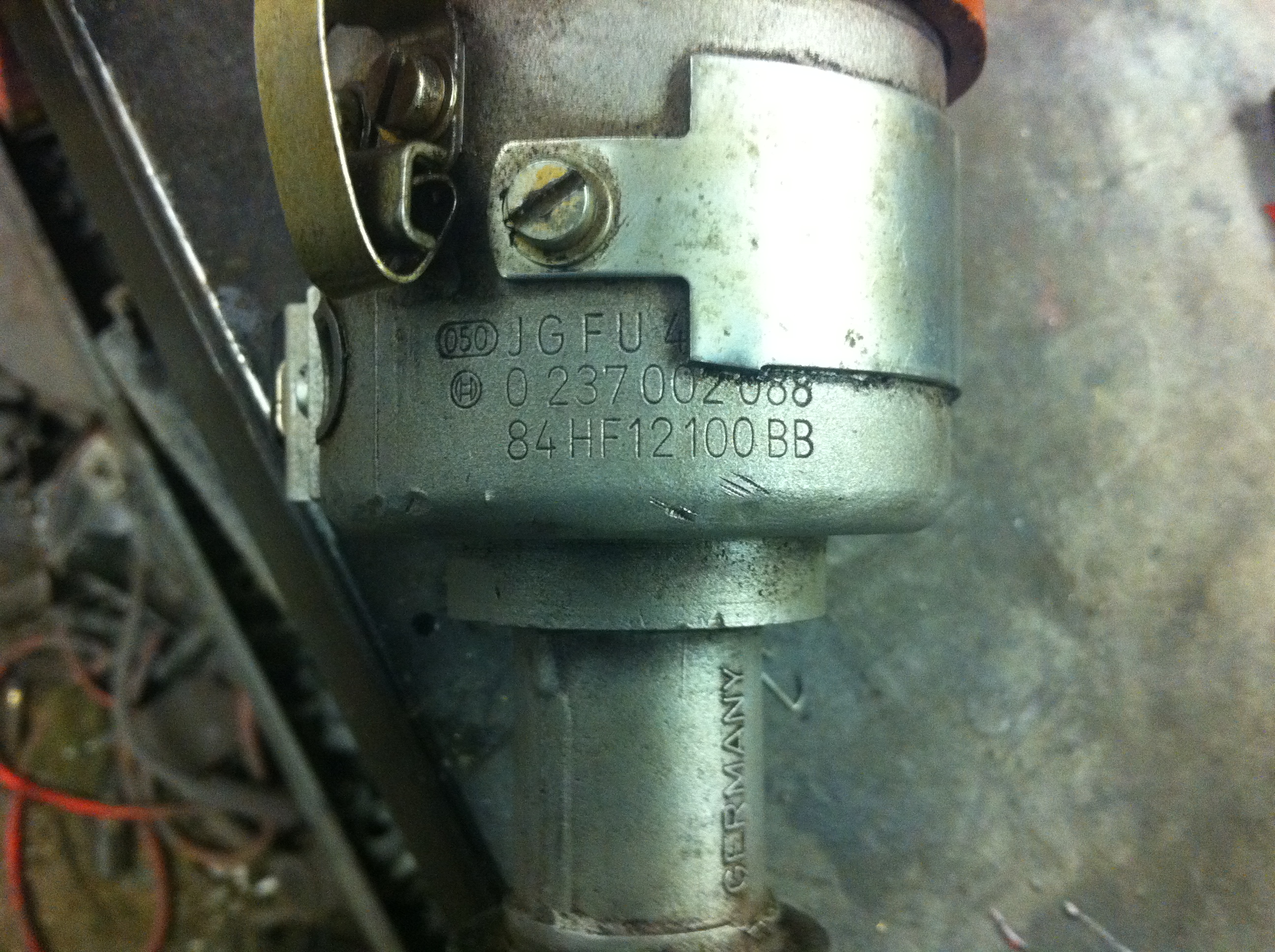
i then have a 3 pin dizzy wire that is using the outer two wires only and they are pluged in on the spare 2 spade terminals of the coil? the dizzy has no points just a black box on the side for the plug, it also doesnt have a vacum advance so how will this be working?
The final question is that i have a 80mm racetech rev counter, how do i wire this up, is it +ve to gauge, earth to gauge, sender wire for coil signal from gauge to green wire -ve side of coil?
It has a motorcraft ignition module with the following wires
brown
green
white
orange
purple
black
the brown is wired to ground,
green -ve side of group a style coil
white cut not used
orange cut not used
purpel cut not used
black +ve side of coil
i then have a 3 pin dizzy wire that is using the outer two wires only and they are pluged in on the spare 2 spade terminals of the coil? the dizzy has no points just a black box on the side for the plug, it also doesnt have a vacum advance so how will this be working?
The final question is that i have a 80mm racetech rev counter, how do i wire this up, is it +ve to gauge, earth to gauge, sender wire for coil signal from gauge to green wire -ve side of coil?
Last edited by coswurv; 23-06-2011 at 09:17 PM.
 22-06-2011, 08:29 PM
#3
This one Ian, had it about a year but only found time recently to do it,
https://passionford.com/forum/restor...track-toy.html
https://passionford.com/forum/restor...track-toy.html
23-06-2011, 09:16 PM
#4
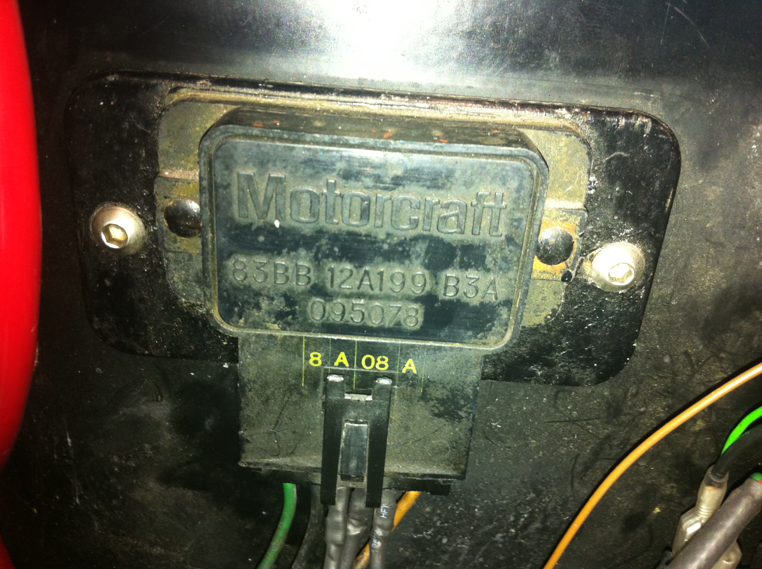
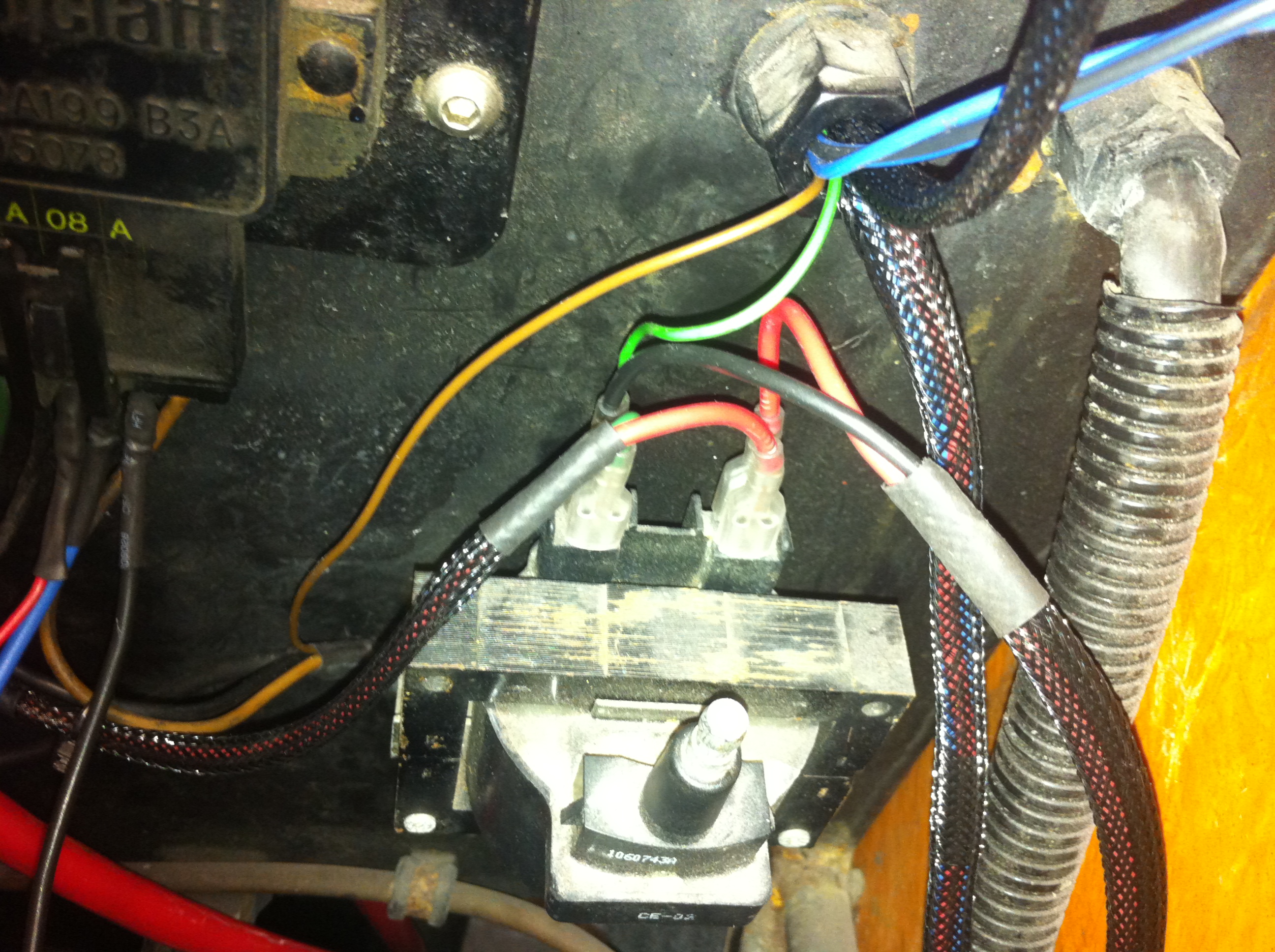
In the above pic is how it was wired when i got the car running, back little green to tacho/black to dizzy, back red to dizzy, front green to ign module, front right red to black wire of ign module, brown wire from ign module to eath, this wiring creates a spark and ran the engine, if i wire it up like this below it wont create a spark ? if i check the purple and orange pins on ign module i get 2.64 volts ? if i then spin the dizzy with a drill i get no voltage change or spark.

Thread
Thread Starter
Forum
Replies
Last Post
JK12
Pictures, video & Photoshop Forum
33
26-04-2021 12:09 PM
3dr cossie
Alloy wheels and ICE for sale
1
02-09-2015 08:58 PM