When you click on links to various merchants on this site and make a purchase, this can result in this site earning a commission. Affiliate programs and affiliations include, but are not limited to, the eBay Partner Network.
Hello!
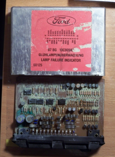
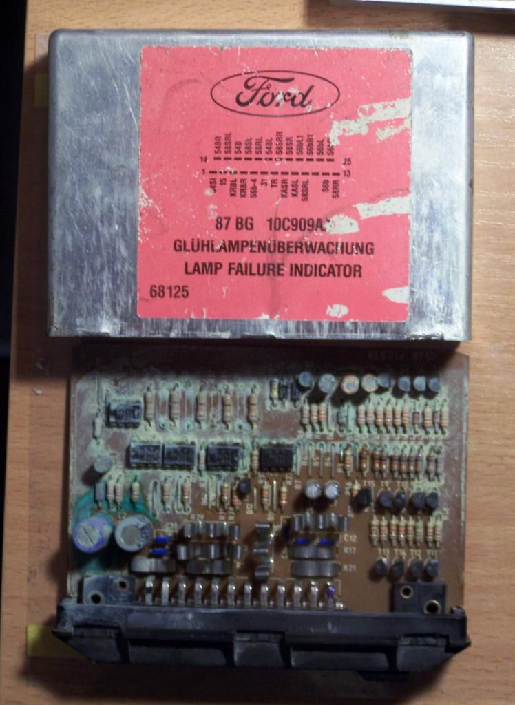
I was wondering, does anyone has internal schematic for the 87BG 10C909AA 'Lamp failure indicator' module?
I recently bought a Sierra (Saph, I think) for spare parts. Well it has this module in, but it's in terrible condition. It was "snowing" green copper rust all over the place when I opened it.
Now, I have an idea... I have this little project to design a computer interface into my Sierra (with touchscreen and stuff), so rather than buying a replacement, I think I will re-engineer this thing into something more modern (and reduce wire count while at it).
If anyone has a schematic for this and is willing to share it, I'd be most thankful. If not, well it may take a while, but I can work it out.
Last edited by JohnLM; 16-11-2014 at 02:18 PM.
Reason: Change title
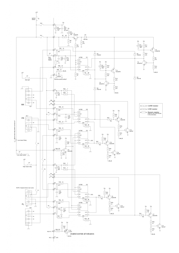
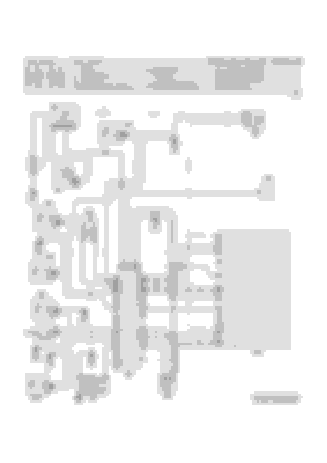
If anyone is interested, I drew a schematic myself.
An example of 80s electronics, it was a good refresher on good old transistors.
The schematic is divided in two parts (by pads and the vertical line). The stuff on the left is all the external connections and are only to get the idea (don't trust it to be exact). The schematic on the right is the module internals, which is exact and tested. (Note two grounds, one is direct to chassis, while the other one is reverse polarity protected by D1 diode)
The PNG is not really good representation. You can drop me a PM and I can send you a PDF or schematic file.
Feel free to post here if you want some info on how this thing works or simply tell if this is useful to you.
Hey do you still have the schemat�c of the lamp failure indicator. I would like to see if I can fix mine as it is showing faulty bulbs where they are working.
Thanks Kobus
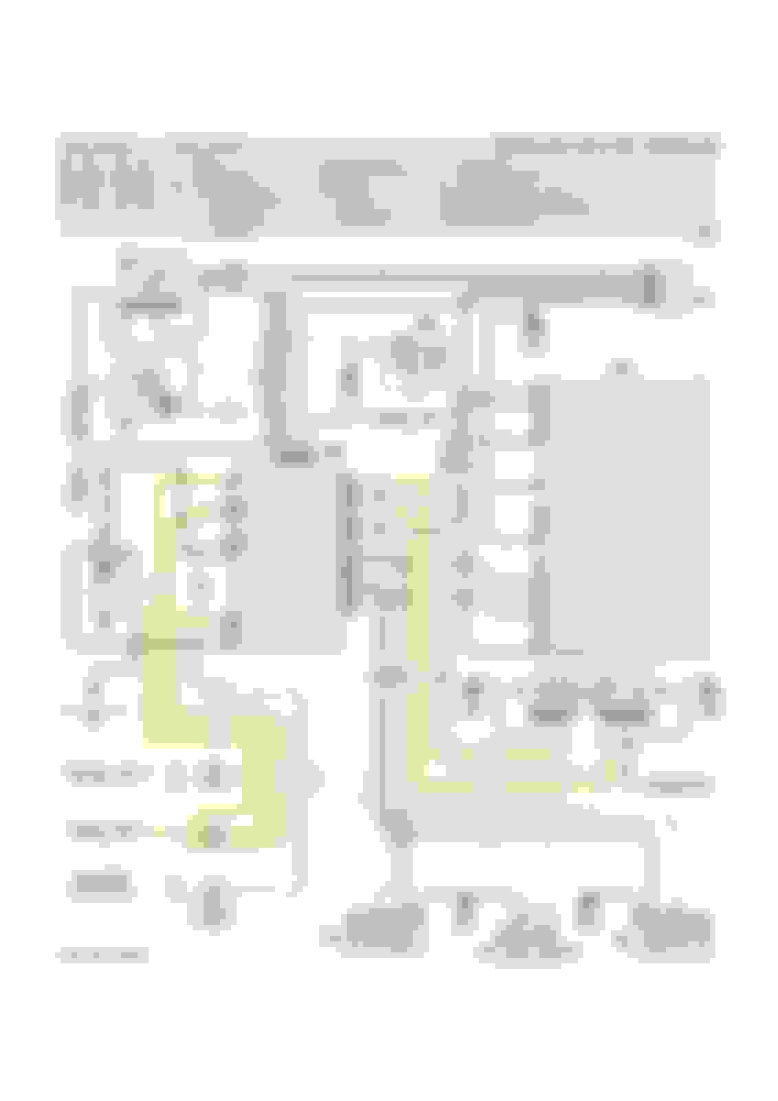
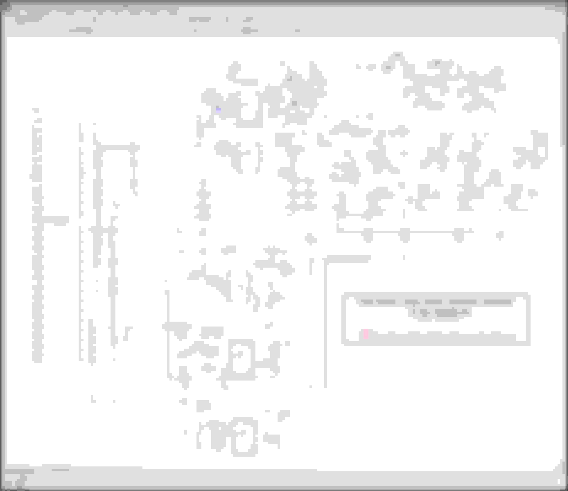
I will attach a couple of diagrams I have which may help you out. John, sorry this is the first time I have come across your post from 2014. Possibly could have saved you a bit of time tracing out the cct. I can't read very well when I zoom in on the cct but it looks like the version of the detecting chips you found in your unit are different to the ones on the cct diagram here. See the other file 'lamp_monitoring' showing the difference between a 477B and 478B. Looks like your cct uses 479B so presumably a different voltage drop model again. Did you ever complete the project to re-engineer the circuitry for this and presumably the Aux warning module. I have attached a circuit diagram for that module here also incase it helps someone. Cheers David
Last edited by 4x4kiwi; 14-07-2019 at 12:50 AM.
Reason: Moved text to top
Hey 4x4kiwi! Thanks for the schematics.
But no, I never finished the project. I hoped to return to it sometime but never realised 5 years had passed
Now, I need to tackle more mundane task on Sierra -- rust.
 11-10-2014, 08:07 PM