Cosworth wiring experts needed!
 05-09-2012, 01:38 AM
#1
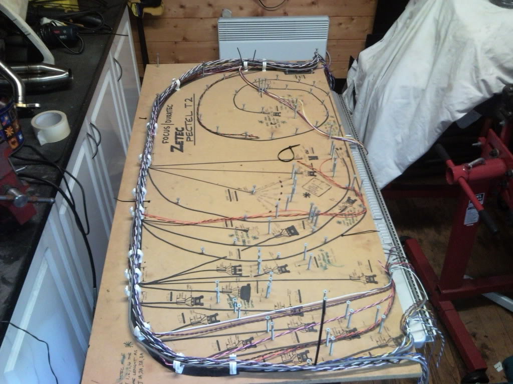
Ive been drawing up a wiring diagram for the new engine loom i plan to make soon.
Had a good look over it a few times and cant see any errors but could do with a few sets of fresh eyes to look over it.
its a basic P8 stand alone loom running a standard coil but "coil pack ready" with all the extra wiring in place. Also wired for antilag via ECU pin 14 and an IECS engine monitor.
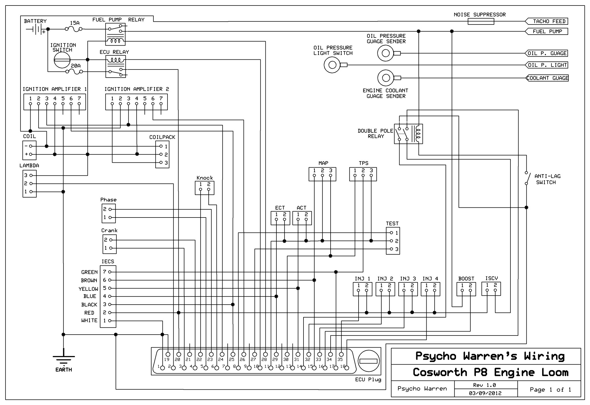
Any comments or advice is welcome!!
Had a good look over it a few times and cant see any errors but could do with a few sets of fresh eyes to look over it.
its a basic P8 stand alone loom running a standard coil but "coil pack ready" with all the extra wiring in place. Also wired for antilag via ECU pin 14 and an IECS engine monitor.
Any comments or advice is welcome!!
Last edited by Psycho Warren; 05-09-2012 at 01:47 AM.

 05-09-2012, 09:20 PM
#6
BANNED
BANNED

Hello Warren,
I know Mike Rainbird has a friend who does his looms who I believe is really trick at them, maybe worth sending him a pm with a print out and a few beers etc
Thats the only fella I can think of mate
I know Mike Rainbird has a friend who does his looms who I believe is really trick at them, maybe worth sending him a pm with a print out and a few beers etc
Thats the only fella I can think of mate
05-09-2012, 09:31 PM
#7
Shall look into that! Im not expecting any professional loom makers to want to help out, even if paid a few beer tokens as its not in thier interests as im making the loom myself!
I was hoping for a few of those whove done thier own looms on here to comment as well.
I already have all the parts bar the braided covering. Im waiting for a stockist of the kevlar braid to have the stuff i want in stock. Kevlar overbraids are far superior but much harder to get and much more expensive.
even using kevlar braid, its still costing me only �170 to make a loom and thats paying retail prices on the parts. If i had a few cars or more loom plans id buy full reels saving shit loads of cash.
no octane adjust needed nor canistor purge.
nothing else you can see?
was thinking of ditching the knock sensor too as some aftermarket looms ive seen dont have the knock plug on them.
I was hoping for a few of those whove done thier own looms on here to comment as well.
I already have all the parts bar the braided covering. Im waiting for a stockist of the kevlar braid to have the stuff i want in stock. Kevlar overbraids are far superior but much harder to get and much more expensive.
even using kevlar braid, its still costing me only �170 to make a loom and thats paying retail prices on the parts. If i had a few cars or more loom plans id buy full reels saving shit loads of cash.
nothing else you can see?
was thinking of ditching the knock sensor too as some aftermarket looms ive seen dont have the knock plug on them.
Trending Topics
05-09-2012, 10:04 PM
#8
I've found that life I needed.. It's HERE!!

Join Date: Feb 2005
Posts: 1,142
Likes: 0
Received 0 Likes
on
0 Posts
Don't forget the map needs screened cable and is connected on map bracket and earth at ecu on std diagram. I am hoping to do my own loom over winter as want to change from level 1 to level 8 and need to add coilpack wiring, lambda and knock sensor so though easier to just make a new one to suit. Only difference to what I need to do is rev counter feed as mine needs to come from pin 21 on ecu as have the msd driver board.
06-09-2012, 04:50 PM
#10
I've found that life I needed.. It's HERE!!
Join Date: Feb 2005
Posts: 1,142
Likes: 0
Received 0 Likes
on
0 Posts
I am pretty sure on my 3 door the earth is on the map sensor bracket, will have to double check. Also not sure if it's worth screening cps and phase sensor as well as I have seen some comments on other posts about this. But they are only earthed at one end if it makes any difference would do this to mine. I am planning to fit new separate battery feed for fuel pump relay, only issue I have is what sized cable to get.

 06-09-2012, 09:48 PM
#16
Too many posts.. I need a life!!

Join Date: Jun 2009
Location: Here and there ...
Posts: 656
Likes: 0
Received 0 Likes
on
0 Posts
At a cursory look, the diagram looks fine - in fact it's easier to read then a majority I've seen before.
Screened cable needs to be used for the MAP sensor, knock sensor and preferably the CPS (although I don't think Ford actually specify this in their original documents). Screened cable should be terminated and earthed at only one end - ideally not the sensor end.
06-09-2012, 11:04 PM
#18
because i currently run a coil but want the loom to be "coilpack ready" for when i next have some tuning/mapping done and can have the coil pack feature switched on.
its switching a relay.
my current set up has 2 switches, one switch to pin 14 of ecu and earth which activates the antilag.
the second switch is in series with the ISCV so that on engine start up the car doesnt rev up to 4k if i leave the ISCV switch on, then when cold the engine revs up lots on startup as the ecu plays around with the ISCV.
by having a relay i can go down to one switch. Sure i could have used a double pole switch but this way i only need run 2 wires across the dash rather than 4. Also if later on i change the antilag to someone elses software which doesnt blip the ISCV, its dead easy to take out the relay.
cheers for the advice on the screening. confirms what someone had said elsewhere.
doesnt directly feed the fuel pump. My battery is in the boot so to garuntee good voltage at the pump it has a direct feed from the battery. The "fuel pump feed" from the cossie loom just triggers the relay in the boot. I guess i could wire the amal valve off the ECU relay and just use an ignition switched wire to the relay in the boot.
its switching a relay.
my current set up has 2 switches, one switch to pin 14 of ecu and earth which activates the antilag.
the second switch is in series with the ISCV so that on engine start up the car doesnt rev up to 4k
if i leave the ISCV switch on, then when cold the engine revs up lots on startup as the ecu plays around with the ISCV.by having a relay i can go down to one switch. Sure i could have used a double pole switch but this way i only need run 2 wires across the dash rather than 4. Also if later on i change the antilag to someone elses software which doesnt blip the ISCV, its dead easy to take out the relay.
At a cursory look, the diagram looks fine - in fact it's easier to read then a majority I've seen before.
Screened cable needs to be used for the MAP sensor, knock sensor and preferably the CPS (although I don't think Ford actually specify this in their original documents). Screened cable should be terminated and earthed at only one end - ideally not the sensor end.
Screened cable needs to be used for the MAP sensor, knock sensor and preferably the CPS (although I don't think Ford actually specify this in their original documents). Screened cable should be terminated and earthed at only one end - ideally not the sensor end.
doesnt directly feed the fuel pump. My battery is in the boot so to garuntee good voltage at the pump it has a direct feed from the battery. The "fuel pump feed" from the cossie loom just triggers the relay in the boot. I guess i could wire the amal valve off the ECU relay and just use an ignition switched wire to the relay in the boot.
07-09-2012, 12:09 AM
#21
correct and the std cars were equipped with screened cable which was revised a number of times throughout the model range and production period
The p8 being more advanced suffered drastically with RF interference
Pectel were employed to resolve the issues the works cars were suffering with, which was cured eventually with their specially made looms which do not use screened cable
Rf interference is extremely complex to identify and cure
whilst we are on the subject of the P8 you have no need of a knock sensor loom as pectel boards and software disable this function for a very specific reason
Last edited by Turbosystems; 07-09-2012 at 12:10 AM.
07-09-2012, 01:16 AM
#22
the ford Escos big turbo wiring diagrams are clearly bollocks then as they are showing a knock sensor as well as earthed shielding on map and knock. good old ford
I'll ditch the knock bit.
did pectel go down the twisted wire route to cancel the interference instead of screened cable? or have they used some fancy wiring material?
good old ford I'll ditch the knock bit.
did pectel go down the twisted wire route to cancel the interference instead of screened cable? or have they used some fancy wiring material?
14-09-2012, 04:44 PM
#23
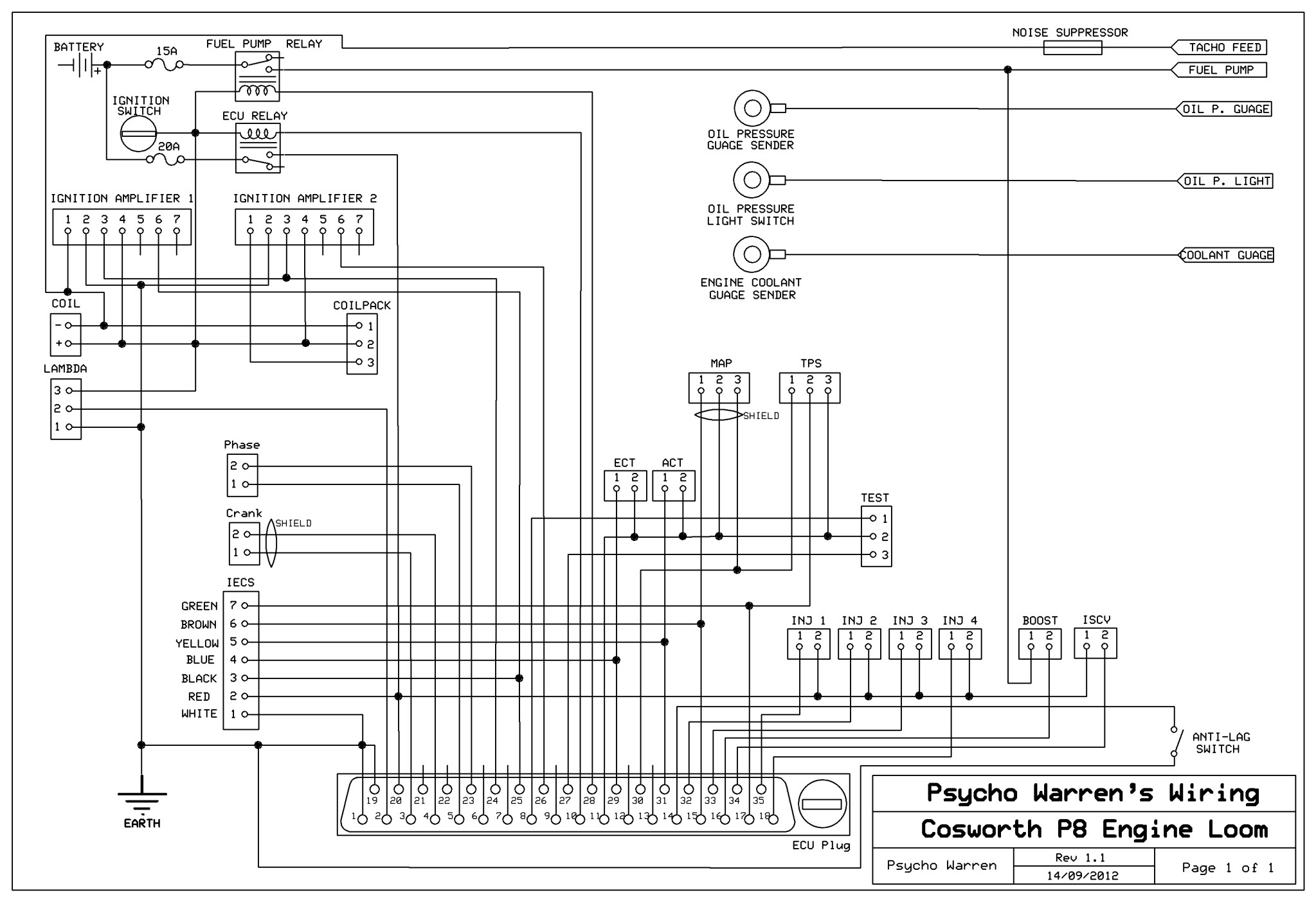
version 1.1
been able to have the software changed slightly so that the ISCV doesnt blip on start up thus meaning no problems on cold start with the engine trying to rev to 4k so no need for a switch on the ISCV circuit. Thus i can ditch the entire anti-lag relay set up and just use the one simple switch solution.
Also ditched knock.

 06-10-2012, 05:53 AM
#28
done a bit more. Still waiting on some kevlar and some terminals arriving as they were out of stock, then i can get on with things a bit more.
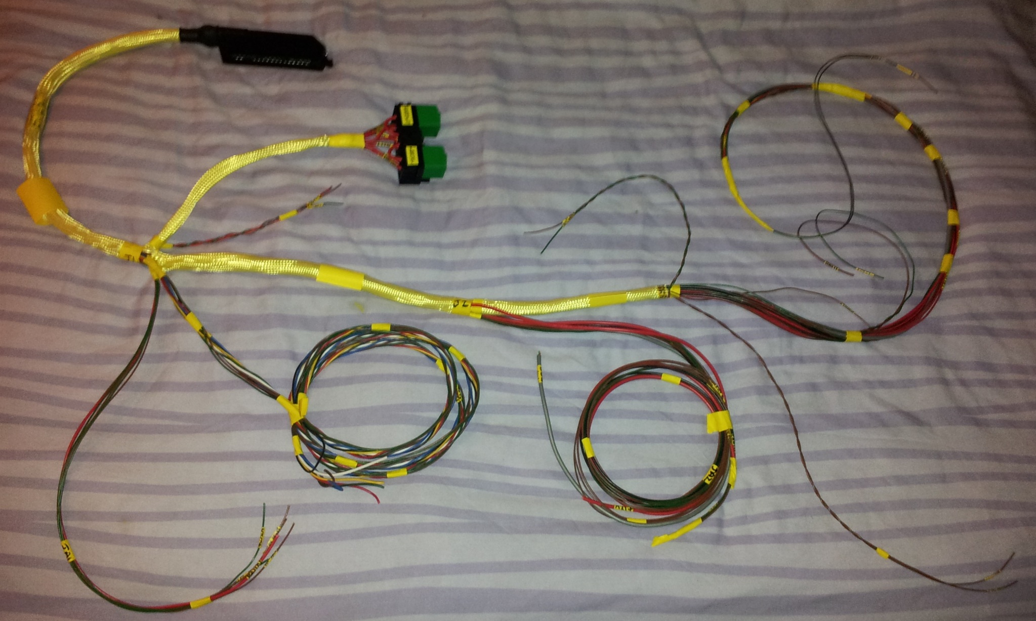
I definitely prefer the kevlar braiding to the plastic braiding. More flexible and seems to be stronger gripped at the ends when its secured.
I definitely prefer the kevlar braiding to the plastic braiding. More flexible and seems to be stronger gripped at the ends when its secured.
06-10-2012, 08:13 AM
#29
Advanced PassionFord User
great work warren , just a little tip if your interested i always make the braid slightly longer and tuck it under the next piece and also every breakout point as when you put the heat shrink on it stops the breakout points sliding out when your bending them around the car
so on the long centre piece of braid working backwards i wouuld make longer along with the first set of breakout points and heat the whole lot together , i also double shrink mine as it makes them abit harder wearing
cheers paul
so on the long centre piece of braid working backwards i wouuld make longer along with the first set of breakout points and heat the whole lot together , i also double shrink mine as it makes them abit harder wearing
cheers paul
06-10-2012, 11:52 AM
#31
Too many posts.. I need a life!!
Join Date: Jul 2003
Location: DUNSTABLE
Posts: 517
Likes: 0
Received 0 Likes
on
0 Posts
Is your heat shrink adhesive lined? As zetecboost said - seeing your fuel relay take off from the main loom sorry to say but it's gonna look untidy 
Your braid should go into the main loom heat shrunk inside and then have another heatshink where it breaks out.
I've done a few looms now and it's harder than it looks to get it looking neat and tidy and then getting it to last without the overbraid pulling out of the heatshink.
Goodluck
Your braid should go into the main loom heat shrunk inside and then have another heatshink where it breaks out.
I've done a few looms now and it's harder than it looks to get it looking neat and tidy and then getting it to last without the overbraid pulling out of the heatshink.
Goodluck
06-10-2012, 01:20 PM
#33
Advanced PassionFord User
i dont know if these will be of any use to you , i lay all wiring out as in the picture , notice there all twisted pairs
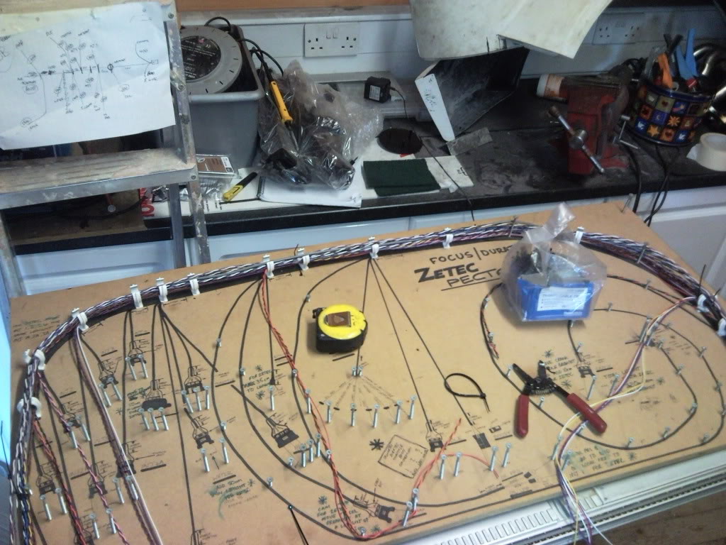
then i braid and heatshrink each breakout point adding around an inch extra so it can slide inside the main loom so it doesnt pull out , sometimes you can have 4 to 5 breakouts at one point so i shrink the whole lot together which then holds them all together and stops the breakout sleeving from pulling out.
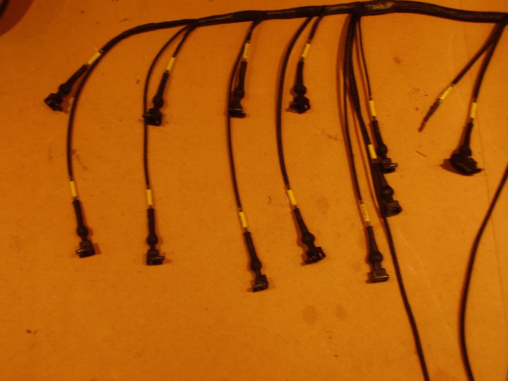
each breakout has an inch underneath the heatshrink

heres a few finished

hope this helps mate
 06-10-2012, 09:24 PM
#34
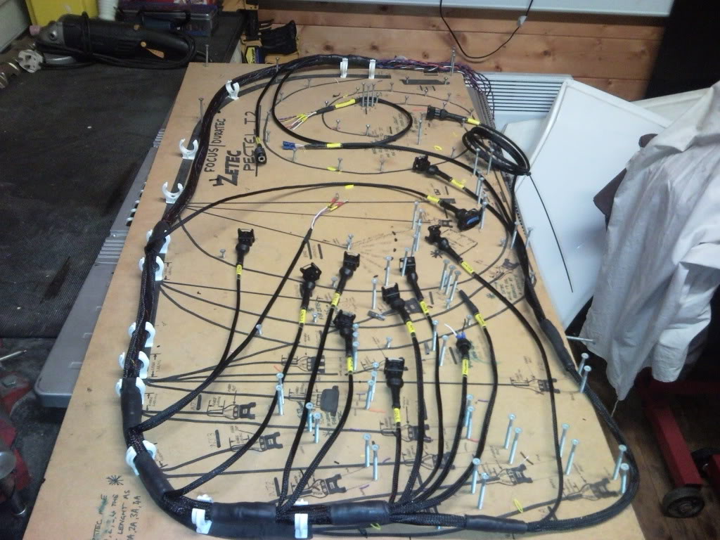
I dont have a spare door lying around otheriwse id pin it out like that as its piss easy that way.
Ive done twisted pairs on all the sensor wiring.
Finally the thin kevlar braid i need for most the two wire breakouts has come back in stock so has been ordered.
Other than that i just need the terminals for the original ford test connector to come back in stock and to print all the labels.
Ive done twisted pairs on all the sensor wiring.
Finally the thin kevlar braid i need for most the two wire breakouts has come back in stock so has been ordered.
Other than that i just need the terminals for the original ford test connector to come back in stock and to print all the labels.
06-10-2012, 09:42 PM
#35
Advanced PassionFord User
I dont have a spare door lying around otheriwse id pin it out like that as its piss easy that way.
Ive done twisted pairs on all the sensor wiring.
Finally the thin kevlar braid i need for most the two wire breakouts has come back in stock so has been ordered.
Other than that i just need the terminals for the original ford test connector to come back in stock and to print all the labels.
Ive done twisted pairs on all the sensor wiring.
Finally the thin kevlar braid i need for most the two wire breakouts has come back in stock so has been ordered.
Other than that i just need the terminals for the original ford test connector to come back in stock and to print all the labels.
cant wait to see the finished product mate , if its anything like your carbon bits it will look shit hot
keep up the good work
cheers paul
06-10-2012, 09:48 PM
#36
i dont think id want to make them for other people unless i got good money for them as its a fair bit of time and hassle. Yet if you want top dollar you have to be 100% confident its perfect for the next 15 to 20 years.As long as mine works I cant complain. Although any new loom is going to be an improvement on a 20 year old saph loom!
 07-10-2012, 12:44 PM
#39
10K+ Poster!!
iTrader: (1)

Join Date: May 2003
Location: Lancashire
Posts: 12,748
Likes: 0
Received 0 Likes
on
0 Posts
Warren.
I've not looked too deeply into your thread but I would run a larger fuse than 20A on the main supply to the management system. I've seen them melt at 20A.
An 044 pump draws about 16A at full chat so I would give it 20A fuse at the power source. If your battery is in the boot then voltage drop won't be as much an issue so you can drop the size of the cable down and also drop the 15A fuse switching your relay in the boot for the fuel pump right down to about 3 amp. A 12V relay only draws about 220MA.
09-10-2012, 05:36 AM
#40
my curent ecu is running a 20A fuse on each relay and hasnt blown yet so i presume when they get really old the resistance in the wiring increases enough to blow them?
Done a bit more now.
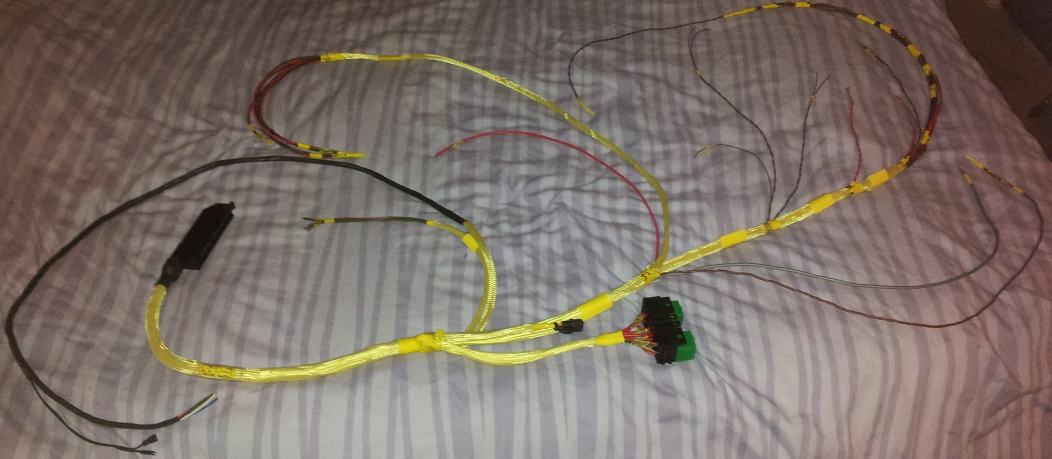
stuck waiting for more braided sleeving to be delivered.
Done a bit more now.
stuck waiting for more braided sleeving to be delivered.

