Digital dials fitting guide (to a mk6 Escort RS2000)
 17-03-2009, 10:33 PM
#1
I'm Finding My Feet Here Now
Thread Starter
First of all you need
Digital dial and multiplug from a MK4/5 Fiesta, Puma or later Escort
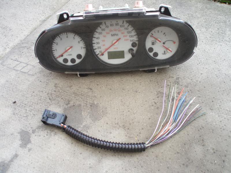
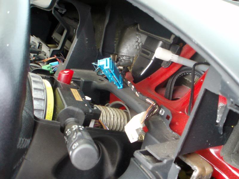
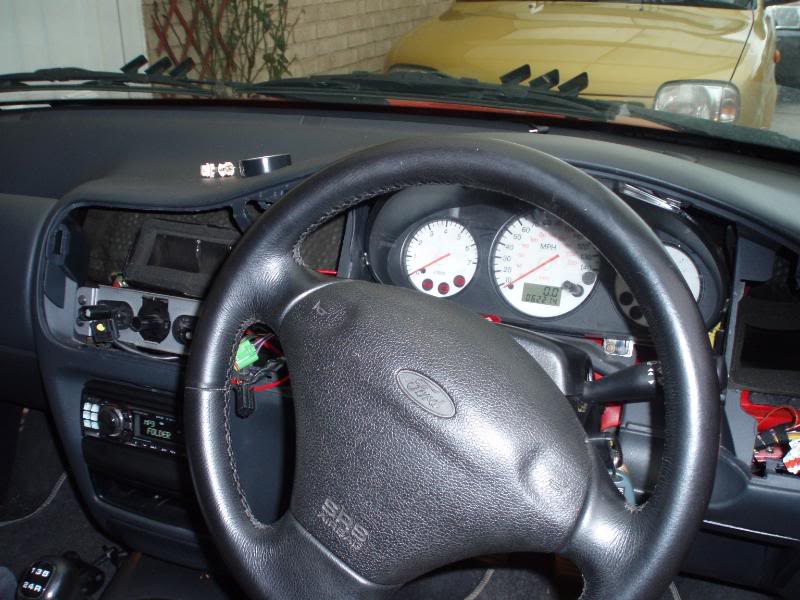
You then need to remove the dash binnicle, original dials.
(see my other guide) Then wire these 2 plugs.....
White plug
1 : Violet – Positive(Switched)
2 : Empty – Low Fuel Warning
3 : Empty - Low Washers Warning
4 : Black/Green – Glow Plug??
5 : Black - Earth
6 : White – Fuel Level
7 : White/Green – Water Temperature
8 : Black/Yellow - Handbrake
9 : 1 Black/Red wire & 1 Black/Green wire - ABS
10 : 2 Black wires - Earth
11 : Violet/White – Main Beam
12 : Orange/Blue - Illumination
Blue Plug
1 : Blue/Black – Indicator (left)
2 : Blue/Green – Indicator (right)
3 : Black/Yellow - Door Ajar Warning
4 : Black/Green – Traction Control Warning
5 : Empty - ??
6 : Black/Green – (Switched Positive)(Goes down to number 12 on BLUE plug)
7 : Blue - Alternator
8 : White/Black - Tachometer
9 : Black/Red - Airbag
10 :White/Green – Oil Warning
11 : Empty - ??
12 : Empty - Positive (Switched??)(Linked from No12 on WHITE plug)
.....to this plug which goes into the back of your new dials
Digi Plug
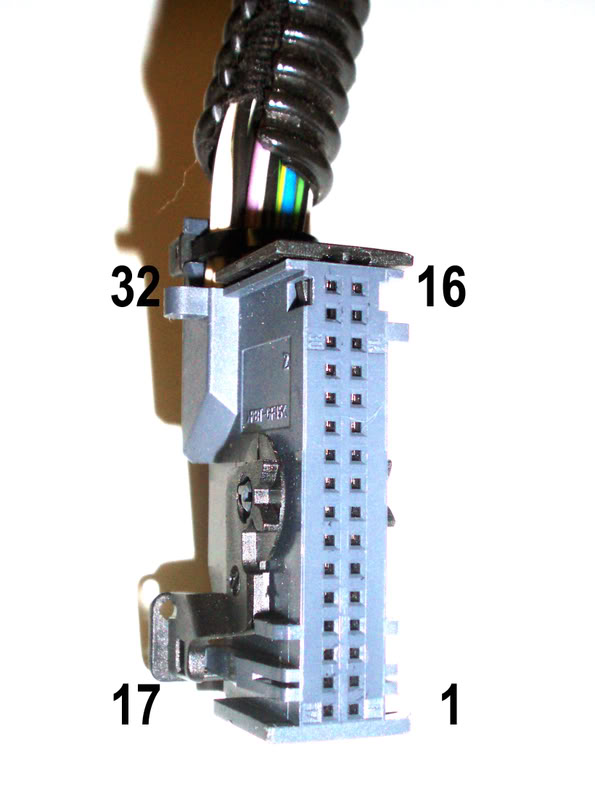
1 permanent 12v (taken from elsewhere as its not in the blue or white plugs)
2 12v switched (on the plugs, linked to pin 22)
3 spare
4 spare
5 spare
6 spare
7 left indicator
8 illumination
9 system monitor (wire to ground)
10 alternator
11 oil indicator
12 handbrake
13 ABS
14 spare
15 spare
16 air bag
17 ground
18 vehicle speed sensor (taken from cable in ecu)
19 spare
20 spare
21 tachometer
22 12v switched (linked to pin 2)
23 fuel s/com (wire to ground)
24 fuel ref (fuel guage)
25 water temperature
26 ground (low wash)
27 ground
28 ground
29 right indicator
30 full beam
31 Door open
32 spare
This is what the wires on mine looked like
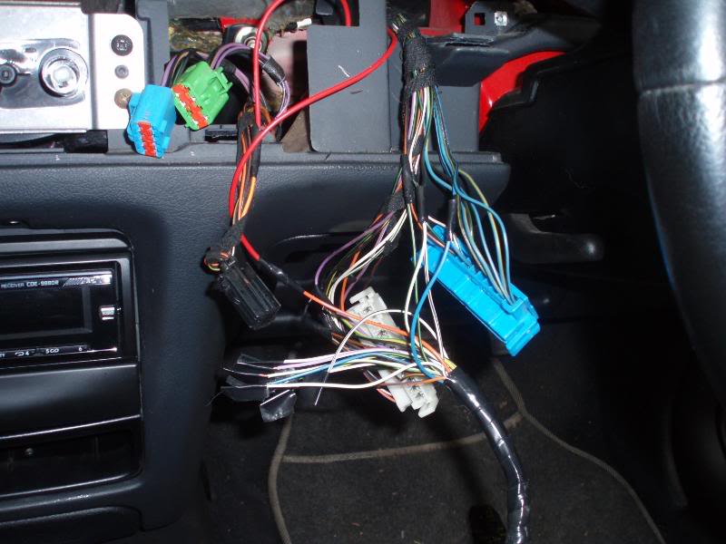
I used the perm live feed from the clock, and spliced into the original wires without cutting the plugs of (just in case
it did n't work), then it can go back to standard dials if needed.
If there are different colours to the wires just just count down
from the blue and white plugs 1 - 12, to find the wire that you need.
Just take your time and double check all wires before connecting.
I did it by first connecting the Perm live, switched live and then
the grounds, then adding one wire at a time i.e handbrake, then turning
on the ignition and seeing if it lit up, after that move on to the next wire, untill they are all done. Then just fit everything back
together and double check that everything works.
The speedo cable will now be useless because the speedometer on
these dials is electrical and takes a feed from the ECU. So you will
need to find out where it is on your ECU. On the RS2000 mk6 (my car)
its on pin 3 on the ECU. The ECU can be found in the front passenger
side footwell, one screw to take off on one side and the other a snap
on fit. Release the single screw securing the ECU and it just pops out.
The fuel pump will need to be removed and the wires switched over that are near/on the float, otherwise the fuel gauge will read in reverse.
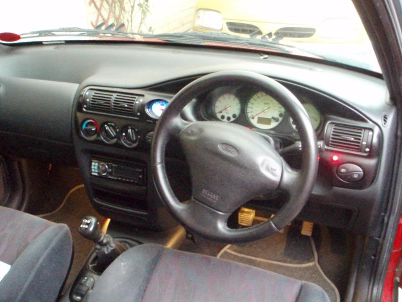
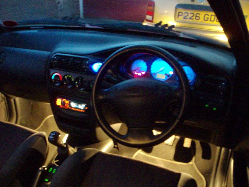
Finished job
Self Diagnostics Mode
The Self Diagnostics Mode gives you in-depth information about your engine and the actual numbers in digital. To use it, follow the steps:
* Insert Key but do not turn it on
* Press and hold the Trip Meter Reset Button
* While holding the reset button, start your car and continue holding the button
* Within 10 seconds, the display should change to "test" in LCD font and the needles will do a full sweeping. Release the Button
Pressing the button will now cycle through some 17 different modes
* 1.Shows a Gauge Sweep
* 2. Shows all 8's on the LCD (LCD TEST)
* 3. Illuminates all the bulbs on the dash
* 4. Displays hexadecimal value for ROM level
* 5. Displays the hexadecimal value for EE level
* 6. Shows DTC (Diagnostic Trouble Code)
* 7. Digital Speedometer - mph
* 8. Digital Speedometer - kph
* 9. N/A
* 10. Digital tachometer
* 11.Fuel volume
* 12. Engine coolant temperature
* 13. Battery voltage
* 14. ABS fail
* 15. Electronic brake distribution (EBD) failure
* 16. Illumination
* 17. Crank Sense
Odometer Display
Description
GAGE Activates gauge sweep of all gauges, then displays present gauge values. Also carries out the checksum tests on ROM and EE. If the gauge sweep is inoperative, INSTALL a new instrument cluster.
All segments illuminated Illuminates all odometer segments. If any odometer segment is inoperative INSTALL a new instrument cluster.
bulb Illuminates all micro-controlled indicators and LEDs. Install a new indicator or LED as necessary.
r Returns to normal operation of all micro-controlled indicators and LEDs and displays hexadecimal value for ROM level. (used when requesting assistance from the hotline). If alternating flashes for FAIL and ROM level are displayed, INSTALL a new instrument cluster.
EE Displays the hexadecimal value for EE level (used when requesting assistance from hotline). If alternating flashes of FAIL and EE level are displayed replace instrument cluster.
dt Displays hexadecimal coding of final manufacturing test date (used when requesting assistance from hotline).
dtc Displays continuous DTC's in hexadecimal format. Pressing the SELECT/RESET button will display any DTCs stored before proceeding to the next step. See index below for description of trouble codes.
enG Displays the English speed in MPH. Speedometer will indicate present speed within tolerances. Display will show 0 if input in not received. If input is invalid for one second or more, or if speed is 0.
m Displays the metric speed data in kph. Speedometer will indicate present speed within tolerances. Display will show 0 if input in not received. If input is invalid for one second or more, or if speed is 0.
tAc Displays the tachometer data received from the PCM via the SCP network within tolerances. Tachometer will indicate present RPM. Display will show 0 if input is no received, if input received is invalid for one second or more, or if engine RPM is 0.
FUEL Displays the code (0-255) for the fuel sender input to the HEC. The fuel gauge will display a filtered fuel level value. This filter will keep the pointer from moving suddenly or erratically.
255 open send +/- 0
232 full stop +/- 0
215 Full mark +/- 10
178 3/4 mark +/- 8
138 1/2 mark +/- 7
93 1/4 mark +/- 5
41 E mark +/- 4
54 Low Fuel (0-59)
0-18 short (0-20 max)
OIL Displays the code (0-250) for the oil pressure switch input to the HEC. Oil pressure gauge will indicate present oil pressure. Normal oil pressure (greater than 6psi) will display a value between 000 and 176. A low oil pressure or an inoperative engine oil pressure switch (less than 6 psi) will display a value greater than 176.
dEGC Display of engine temperature in Degrees C input from cylinder head temperature sensor.
49 C "C" mark
60 C Normal band start
120 C Normal band end
-40 C No SCP message for 5 seconds
bAtt Displays the code (0-255) for the battery voltage input to the HEC. Battery voltage gauge will indicate present battery voltage.
93-102 6.2-9.1 volts, low voltage
115-124 8.5-10.7 volts, Normal band start
215-225 15.8-18 volts, Norm band end
230-241 16.9-19.1 volts, high voltage
rhEo Displays the present decimal rheostat dimming input, 0-255 (used when requesting assistance from the hotline)
rhi
rhS
rho Not used.
Cr Displays the current RUN/START sense input. Display will show -h for high input with the ignition switch in the START position and -L for low input with the ignition switch in the RUN position.
PA-PE7 not used.
GAGE Repeats the display cycle
Blue LEDs fitted
PLEASE NOTE
I WILL NOT BE LIABLE FOR ANYONE WIRING THEIR
CARS WRONG AND SETTING THEMSELVES OR THEIR
CAR ON FIRE!!!!!!!!!!!!!!!!!!!!!!!!
Digital dial and multiplug from a MK4/5 Fiesta, Puma or later Escort
You then need to remove the dash binnicle, original dials.
(see my other guide) Then wire these 2 plugs.....
White plug
1 : Violet – Positive(Switched)
2 : Empty – Low Fuel Warning
3 : Empty - Low Washers Warning
4 : Black/Green – Glow Plug??
5 : Black - Earth
6 : White – Fuel Level
7 : White/Green – Water Temperature
8 : Black/Yellow - Handbrake
9 : 1 Black/Red wire & 1 Black/Green wire - ABS
10 : 2 Black wires - Earth
11 : Violet/White – Main Beam
12 : Orange/Blue - Illumination
Blue Plug
1 : Blue/Black – Indicator (left)
2 : Blue/Green – Indicator (right)
3 : Black/Yellow - Door Ajar Warning
4 : Black/Green – Traction Control Warning
5 : Empty - ??
6 : Black/Green – (Switched Positive)(Goes down to number 12 on BLUE plug)
7 : Blue - Alternator
8 : White/Black - Tachometer
9 : Black/Red - Airbag
10 :White/Green – Oil Warning
11 : Empty - ??
12 : Empty - Positive (Switched??)(Linked from No12 on WHITE plug)
.....to this plug which goes into the back of your new dials
Digi Plug
1 permanent 12v (taken from elsewhere as its not in the blue or white plugs)
2 12v switched (on the plugs, linked to pin 22)
3 spare
4 spare
5 spare
6 spare
7 left indicator
8 illumination
9 system monitor (wire to ground)
10 alternator
11 oil indicator
12 handbrake
13 ABS
14 spare
15 spare
16 air bag
17 ground
18 vehicle speed sensor (taken from cable in ecu)
19 spare
20 spare
21 tachometer
22 12v switched (linked to pin 2)
23 fuel s/com (wire to ground)
24 fuel ref (fuel guage)
25 water temperature
26 ground (low wash)
27 ground
28 ground
29 right indicator
30 full beam
31 Door open
32 spare
This is what the wires on mine looked like
I used the perm live feed from the clock, and spliced into the original wires without cutting the plugs of (just in case
it did n't work), then it can go back to standard dials if needed.
If there are different colours to the wires just just count down
from the blue and white plugs 1 - 12, to find the wire that you need.
Just take your time and double check all wires before connecting.
I did it by first connecting the Perm live, switched live and then
the grounds, then adding one wire at a time i.e handbrake, then turning
on the ignition and seeing if it lit up, after that move on to the next wire, untill they are all done. Then just fit everything back
together and double check that everything works.
The speedo cable will now be useless because the speedometer on
these dials is electrical and takes a feed from the ECU. So you will
need to find out where it is on your ECU. On the RS2000 mk6 (my car)
its on pin 3 on the ECU. The ECU can be found in the front passenger
side footwell, one screw to take off on one side and the other a snap
on fit. Release the single screw securing the ECU and it just pops out.
The fuel pump will need to be removed and the wires switched over that are near/on the float, otherwise the fuel gauge will read in reverse.
Finished job
Self Diagnostics Mode
The Self Diagnostics Mode gives you in-depth information about your engine and the actual numbers in digital. To use it, follow the steps:
* Insert Key but do not turn it on
* Press and hold the Trip Meter Reset Button
* While holding the reset button, start your car and continue holding the button
* Within 10 seconds, the display should change to "test" in LCD font and the needles will do a full sweeping. Release the Button
Pressing the button will now cycle through some 17 different modes
* 1.Shows a Gauge Sweep
* 2. Shows all 8's on the LCD (LCD TEST)
* 3. Illuminates all the bulbs on the dash
* 4. Displays hexadecimal value for ROM level
* 5. Displays the hexadecimal value for EE level
* 6. Shows DTC (Diagnostic Trouble Code)
* 7. Digital Speedometer - mph
* 8. Digital Speedometer - kph
* 9. N/A
* 10. Digital tachometer
* 11.Fuel volume
* 12. Engine coolant temperature
* 13. Battery voltage
* 14. ABS fail
* 15. Electronic brake distribution (EBD) failure
* 16. Illumination
* 17. Crank Sense
Odometer Display
Description
GAGE Activates gauge sweep of all gauges, then displays present gauge values. Also carries out the checksum tests on ROM and EE. If the gauge sweep is inoperative, INSTALL a new instrument cluster.
All segments illuminated Illuminates all odometer segments. If any odometer segment is inoperative INSTALL a new instrument cluster.
bulb Illuminates all micro-controlled indicators and LEDs. Install a new indicator or LED as necessary.
r Returns to normal operation of all micro-controlled indicators and LEDs and displays hexadecimal value for ROM level. (used when requesting assistance from the hotline). If alternating flashes for FAIL and ROM level are displayed, INSTALL a new instrument cluster.
EE Displays the hexadecimal value for EE level (used when requesting assistance from hotline). If alternating flashes of FAIL and EE level are displayed replace instrument cluster.
dt Displays hexadecimal coding of final manufacturing test date (used when requesting assistance from hotline).
dtc Displays continuous DTC's in hexadecimal format. Pressing the SELECT/RESET button will display any DTCs stored before proceeding to the next step. See index below for description of trouble codes.
enG Displays the English speed in MPH. Speedometer will indicate present speed within tolerances. Display will show 0 if input in not received. If input is invalid for one second or more, or if speed is 0.
m Displays the metric speed data in kph. Speedometer will indicate present speed within tolerances. Display will show 0 if input in not received. If input is invalid for one second or more, or if speed is 0.
tAc Displays the tachometer data received from the PCM via the SCP network within tolerances. Tachometer will indicate present RPM. Display will show 0 if input is no received, if input received is invalid for one second or more, or if engine RPM is 0.
FUEL Displays the code (0-255) for the fuel sender input to the HEC. The fuel gauge will display a filtered fuel level value. This filter will keep the pointer from moving suddenly or erratically.
255 open send +/- 0
232 full stop +/- 0
215 Full mark +/- 10
178 3/4 mark +/- 8
138 1/2 mark +/- 7
93 1/4 mark +/- 5
41 E mark +/- 4
54 Low Fuel (0-59)
0-18 short (0-20 max)
OIL Displays the code (0-250) for the oil pressure switch input to the HEC. Oil pressure gauge will indicate present oil pressure. Normal oil pressure (greater than 6psi) will display a value between 000 and 176. A low oil pressure or an inoperative engine oil pressure switch (less than 6 psi) will display a value greater than 176.
dEGC Display of engine temperature in Degrees C input from cylinder head temperature sensor.
49 C "C" mark
60 C Normal band start
120 C Normal band end
-40 C No SCP message for 5 seconds
bAtt Displays the code (0-255) for the battery voltage input to the HEC. Battery voltage gauge will indicate present battery voltage.
93-102 6.2-9.1 volts, low voltage
115-124 8.5-10.7 volts, Normal band start
215-225 15.8-18 volts, Norm band end
230-241 16.9-19.1 volts, high voltage
rhEo Displays the present decimal rheostat dimming input, 0-255 (used when requesting assistance from the hotline)
rhi
rhS
rho Not used.
Cr Displays the current RUN/START sense input. Display will show -h for high input with the ignition switch in the START position and -L for low input with the ignition switch in the RUN position.
PA-PE7 not used.
GAGE Repeats the display cycle
Blue LEDs fitted
PLEASE NOTE
I WILL NOT BE LIABLE FOR ANYONE WIRING THEIR
CARS WRONG AND SETTING THEMSELVES OR THEIR
CAR ON FIRE!!!!!!!!!!!!!!!!!!!!!!!!

The following 2 users liked this post by trev27:
patrickg (25-03-2021),
rextreme23 (19-03-2022)
25-11-2009, 10:09 PM
#2
can you smell purple?
Join Date: Sep 2009
Location: normally dewsbury west yorkshire, but i could wake up anywhere!
Posts: 459
Likes: 0
Received 0 Likes
on
0 Posts
you clever sod its as good as standard.
just a Q' what led bulbs did you use on the the clock (not the new fancy digital cluster)
p.s good job on the "how to" guide on another forum for led switch conversions.
its as good as standard.just a Q' what led bulbs did you use on the the clock (not the new fancy digital cluster)
p.s good job on the "how to" guide on another forum for led switch conversions.
 18-08-2010, 03:03 PM
#4
I'm Finding My Feet Here Now
Thread Starter
hold the trip button in, then start engine keeping the button pressed in still the word test appears on the display, then release. Scroll through all the available parameters by pressing the button in.
09-10-2010, 09:51 PM
#5
15000
Join Date: Oct 2007
Location: France
Posts: 39
Likes: 0
Received 0 Likes
on
0 Posts
Thanks for your guide
I changed mine but i have a problem with the water temperature guage.
The guage stays in the middle even if the engine is hot (fan on).
Have you an idea?
I changed mine but i have a problem with the water temperature guage.
The guage stays in the middle even if the engine is hot (fan on).
Have you an idea?

") 12-06-2011, 07:32 PM
12-06-2011, 07:32 PM
#7
Works and plays on track
Trending Topics
 24-03-2012, 05:50 PM
#10
Back By Dope Demand

Hi, I have a question about reversing the fuel gauge wires. I have located them but if i swap the fuel gauge sender wire for its earth i get the same response(no fuel in car, gauge showing full). Any ideas? Have I just missed something? Any advise gratefully received. Thanks  PS Thanks for the guide, made everything simple
13-06-2014, 09:53 PM
#11
Virgin

Join Date: Oct 2013
Location: Bulgaria
Posts: 8
Likes: 0
Received 0 Likes
on
0 Posts
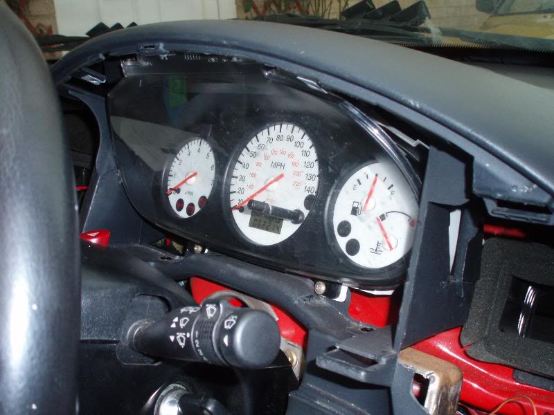
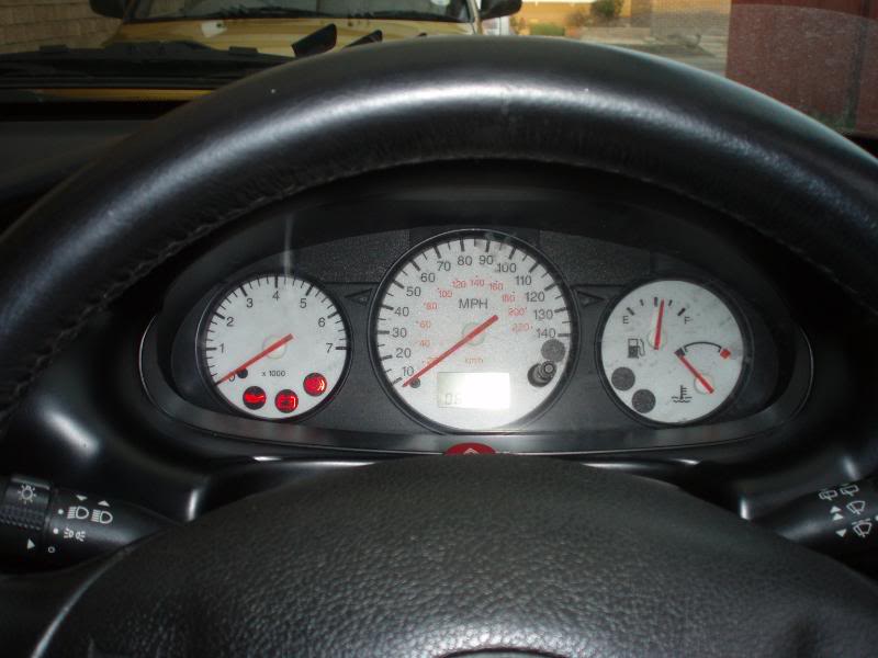
there is another version of the digital dashboard.
It has little difference, the airbag is above the fuel level not under 140mph, and the light under 140mph is for opened door/s. There are other different things too but thats enough.
Also the wired pins in the wiring harness are a bit different.
pin25 for the engine temp is missing a wire. You have to take a spare one and put it there.
There is also error in the description of the blue plug pinout!
the airbag is on pin 6! What's said above in brackets is wrong
here are pics of the original dash so you can see for yourself:
25-03-2021, 03:46 PM
#12

Good afternoon,
I read the post of converting digital cluster to mk6, the post is very detailed, I would like to ask since the cluster is digital etc, there is na need of a sort of programming?. or after the wiring will just work fine?
Patrick
I read the post of converting digital cluster to mk6, the post is very detailed, I would like to ask since the cluster is digital etc, there is na need of a sort of programming?. or after the wiring will just work fine?
Patrick
25-03-2021, 03:49 PM
#13
Good afternoon,
I read the post of converting digital cluster to mk6, the post is very detailed, I would like to ask since the cluster is digital etc, there is na need of a sort of programming?. or after the wiring will just work fine?
Patrick
I read the post of converting digital cluster to mk6, the post is very detailed, I would like to ask since the cluster is digital etc, there is na need of a sort of programming?. or after the wiring will just work fine?
Patrick
The following users liked this post:
rextreme23 (19-03-2022)


Thread
Thread Starter
Forum
Replies
Last Post
Graceland
General Car Related Discussion.
16
20-05-2011 06:33 PM